Needing more than a spark test?

I trawled all the OLD FETs, compared specs, discovered those now supposedly equivalent and overpriced for audiophiles.
Then I found, from Mouser, the SMP147, which of course, is a modern 2SK147.
There was also, from Mouser, the suitable looking NSVJ3557SAT1G.
I did not choose to try for like the Linear Systems LSK389, and LSK170.

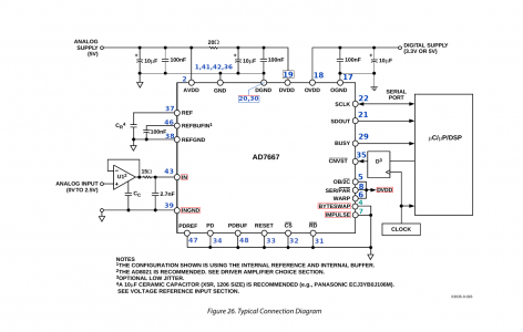
In getting the design together, I am mindful of what other folk might consider essential. For example, if you are using the AD7667, would you be using the recommended AD8021 opamp driver in gain=1 mode as shown in Figure 26.

I trawled all the OLD FETs, compared specs, discovered those now supposedly equivalent and overpriced for audiophiles.
Then I found, from Mouser, the SMP147, which of course, is a modern 2SK147.
There was also, from Mouser, the suitable looking NSVJ3557SAT1G.
I did not choose to try for like the Linear Systems LSK389, and LSK170.

In getting the design together, I am mindful of what other folk might consider essential.
Here we need to check in with @homebrewed . Mark is going to be using the AD7667 ADC,
That ADC uses 2.5V reference. The ADC I use has 2.048V reference, and the power supplies are appropriately different, although that is just a matter of labeling.

If you would also be using the AD7667, would you be using the recommended AD8021 opamp driver in gain=1 mode as shown in Figure 26 ?
The tracking for my differential driver happens to have the same pinout as AD8022 dual driver. It should be easy to arrange the tracking so that it has the driver, and one available opamp for signal conditioning gain.

Mark is interfacing to Teensy, and I think he is grabbing bytes in parallel, so if you are using common software, you would naturally choose to use the AD7667. If you want to be taking off the numbers serially, using SPI, as I intend to, then either will do. I will try to include any stuff you folk request. It is a prototype board anyway. Quite a lot of bits here and there will end up not being populated.
I would be willing to try a SPI input for the ADC. What SPI rate would be needed?

Not so sure about where Fig. 26 is, but I'd probably go for the recommended driver. Generally that's a good idea, especially when just getting things to work.
 
Interesting that your compiler is picky about statement indentation. Looking at all the complaints about char buff[32], it looks to me like they're all related to the compiler backtracking GetString(buff, 32) and finding a possibility of writing past the end of the buffer. To test that, the easiest thing to do is to increase the length of the buffer, say: char buff[34] and see what happens.
You'd think it was checking Python! I never thought it would complain about indents... gcc never used to care about that. I don't mind cleaning that sort of stuff up, personally I like the spacing that Python enforces. I try to make my C code in a similar fashion.

I'll try increasing the buffer size and see what happens.
Edit: that got rid of the buff warnings. I cleaned up some of the formatting and it is happier. Only complaining about pflag. There's something funky about your indentation. Don't know if that is responsible for the pflag warning. Maybe a scope issue, but I don't see how yet.
 
Last edited:
You'd think it was checking Python! I never thought it would complain about indents... gcc never used to care about that. I don't mind cleaning that sort of stuff up, personally I like the spacing that Python enforces. I try to make my C code in a similar fashion.

I'll try increasing the buffer size and see what happens.
Maybe the computer language world is converging on PyCpp..... <lame joke>

On a slightly different subject (actually about machining!) I shaved off about as much of my aluminum focusing ring as I could. I first had to pop it off my lead shield plate since I had glued it down. It now has a fresh dab of 2-part epoxy setting up. Hopefully I can get some results by the end of the day.

I have decided I also need to make a plastic ring to replace the aluminum I removed. The focusing ring also serves as a reference surface for installing the source assembly. That's important because it establishes the distance from the detector to the sample....
 
I would be willing to try a SPI input for the ADC. What SPI rate would be needed?

Not so sure about where Fig. 26 is, but I'd probably go for the recommended driver. Generally that's a good idea, especially when just getting things to work.
Given that the pinout of both ADCs is pretty near identical, I want to make my board support both. It seems entirely possible. I need to ask how fast the Teensy can wiggle its SPI interface. It's a very fast little computer. It should be able to load in serial bytes at the speed you want the ADC to sample, but I don't know. I preferred the serial way in, a whole 16 bits at a time, instead of hauling in smaller chunks in parallel.

You can use either. The AD7667 can run 800kSPS in "normal" mode, and 1MSPS in "warp mode".
The AD7622 that I intend using runs 1.5MSPS in "normal mode", and 2 MSPS in "wideband and warp mode".
There are some inconveniences in running warp mode.

An example
The way to work it is to decide how many samples are good for a pulse. If you are using the "slowed down" version, then you can increase the number of samples in a pulse. Suppose we consider the slowest version.

e.g. Using the AD7667 at 800 kSPS. Suppose you decide 20 samples out of a pulse is reasonable. That means you take out a 16-bit number at 40kHz. So far as Teensy managing to clock out SPI at this rate, I would think it would be easy. Teensy is a 600MHz thing.
Now look further..
This rate forces that you have 25uS allowed for every complete pulse event. My simulations of the stretched pulse Pocket Geiger circuit show that the pulse duration is about ten times that, which is why I consider the Pocket Geiger circuit unviable in this application.
To make it work does not require any changes to ADC speed, only to the bandwidth of the amplifier chain.

Going slower.
Of course, if the need to process a pulse does not happen very often, then things get easy.
You can decide that 240uS is the time for a slowed down stretched out pulse.
I have my misgivings about those, but for now, I have to accept the notion is OK.

If you can take 800 kSMPS from the ADC, that means there is 1.25uS needed for a sample. For the whole pulse event rate, that allows as many as 192 fine-grained samples during that slow pulse, if you want to use that many.
Either way, the Teensy is gathering 16-bits every 240uS, or at 4166.6Hz. I am pretty sure a Teensy would be loafing along.

The arrival rate.
This is the big unknown for me. It affects my choice of how many sources to mount, currently eight. I may have a separate posting on that subject soon. if indeed, we can only expect an arrival at 1Hz rate, then I am going to try and max out on the sources, but by every other calculation I have done, I was expecting hundreds of Hz, up to several kHz. I need to find out what is not happening.

About the driver for the ADC.
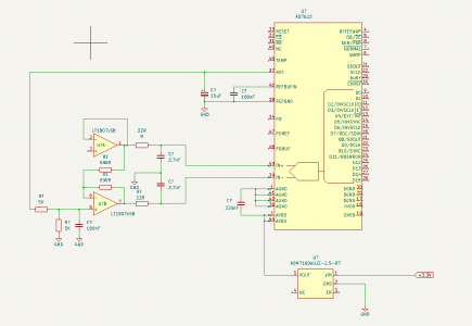
Take a look at driver U1 with Note (2). As it happens, the dual version of that driver, AD8022, has the same pinout as LT1807 I use for driving my AD7622. So now compare the driver stuff.

AD7667 Pins.png

Here is my circuit for the very similar ADC, and it's track-compatible driver.

AD7622 ADC.png

If you used AD8021 recommended driver, you get the same result, using AD8022 dual version, with one opamp left over, usable for something else, like gain. Come to that, the LT1807 would do the same job. The difference in the circuit tracking can be managed with links. Putting a zero ohms resistor in place of one of the capacitors to ground pin 39, converts it to using the AD7667 ADC.
 
Last edited:
The trigger point is fixed so the bulk of the pulse moves back & forth depending on its amplitude. The other thing I keep worrying about is minimizing the effect of pulse overlap on the system's FWHM.

I'm currently thinking that a substantial part of the issue is the leading edge of the pulse. It has a much shorter risetime compared to the fall time. this is because the risetime is mostly determined by the bandwidth of everything beyond the TIA, while the fall time is mostly determined by the TIA. So getting that leading edge nailed down is critical for getting as-sharp-as-possible XRF spectrums.
I do agree, and it's not too hard to have that happen. Just changing the gain distribution, and using the available gain opportunity on the signal conditioning board gets you there.

I cannot think we have to deal with input currents for a arrival pulse of less than 40pA, and the circuit can see to values less than that. It can use a 100pA input to max out 2.4V at the other end. It also preserves the risetime.

I don't know yet, but I am thinking that if the pulse duration you are trying to sample moves across and back, depending on when it's rise happened to cross a fixed trigger, there is potential for all sorts of jitter. If the ADC was sampling at a constant, unrelenting, fixed rate, regardless, sometimes seeing invalid OTT pulses, or spending too long with ton of pulses all keeping coming on to pf one another, that's OK.

Once a trigger pulse is seen, the ring buffer is addressed at a point some samples down the line pre-trigger, tested for being low enough to be a good place to start, and then counting from there, one pulse duration's worth of samples is taken off. There is a test for the last sample being below some threshold, near zero, or that is evidence another pulse overlapped. We don't let the trigger event mess with our count. Count a whole pulse.

I know this sounds simplistic, and I may end up using all the stuff you have found out one has to do, because you have the actual thing powered, and have experience with it. Right now, what I have are my calculations, simulations, the part finished lead shield design with the need to melt the stuff next to me, and the KiCad circuit, incorporating all the best stuff I can gather. I also have a never-ending list of boring other home stuff that won't go away!

I will send you one of my boards, but I think, in a different physical form, you already have everything.
 
Teensy should run a 35MHz SPI without issues. I've heard some people doing 60MHz but don't know if that is fact or fiction. About 35MHz is more than fast enough to clock in 16bits at 1 MS/s. I don't know if it can be easily pushed to 2MS/s.

There is a FlexIO on Teensy that should allow much faster transfers, it's minimum clock is 49MHz, but I have been unable to find a single working example of that. I don't think that is something I want to tackle. It makes me nervous when the guy that designed these boards says it ought to run that fast, but has not been able to get it to work...
 
Maybe the computer language world is converging on PyCpp..... <lame joke>

On a slightly different subject (actually about machining!) I shaved off about as much of my aluminum focusing ring as I could. I first had to pop it off my lead shield plate since I had glued it down. It now has a fresh dab of 2-part epoxy setting up. Hopefully I can get some results by the end of the day.

I have decided I also need to make a plastic ring to replace the aluminum I removed. The focusing ring also serves as a reference surface for installing the source assembly. That's important because it establishes the distance from the detector to the sample....
Did I mention that if a photon sees a plastic, it may spray little outputs too low energy for us to detect, but also has the unused left over (high) energy remainder as exit photons, spraying out in any and all directions, including straight at the diode? What stops it is lead Pb. I don't think much else does.
 
Last edited:
Teensy should run a 35MHz SPI without issues. I've heard some people doing 60MHz but don't know if that is fact or fiction. About 35MHz is more than fast enough to clock in 16bits at 1 MS/s. I don't know if it can be easily pushed to 2MS/s.

There is a FlexIO on Teensy that should allow much faster transfers, it's minimum clock is 49MHz, but I have been unable to find a single working example of that. I don't think that is something I want to tackle. It makes me nervous when the guy that designed these boards says it ought to run that fast, but has not been able to get it to work...
Look for Teensy SPI info from the data sheet. Even disregard what other folk posing on the net get up to. I won't be using Teensy, but I know it is fast enough to manage quite fine. The bottleneck is not Teensy.

At even (say) 20MHz SPI, that is 50nS period. Suppose it's clocking out a 16-bits, and allow that there has to be other clocks with it, even if as much as 32 clocks. that is still 1.6uS for the whole thing. You would be filling the ring buffer with 16-bit words at 625kHz!

In the circuit we are currently considering, it goes a whole lot slower than that!

[Edit: Can I assume that you want one of the boards? ]
 
Last edited:
Teensy is a 600MHz thing.
Its CPU can run at that speed but its I/O stuff is run off a slower clock. The fastest benchmark I got for directly reading a GPIO was 75Mbytes/second; and that included a couple of shifts (although that occurred @600 MHz) to combine 2 nybbles into an 8-bit value. It _might_ be possible to increase the I/O clock but I haven't looked into it that much.

The audio ADC board that PJRC sells has been successfully operated well above its nominal 44KSPS -- IIRC, close to 300KSPS; and it uses a special serial interface specifically designed for digital audio. But it may not be able to run fast enough to achieve 1MSPS or higher. That was demonstrated in a fairly sophisticated SDR a fellow built using the Teensy to both acquire downconverted signals AND filter them using its built-in DSP capabilities

The T4.x FlexIO subsystem also may work but it's been difficult to figure out how to use it (for me, at least). It's attractive because it can be configured to include a buffer that would help to reduce the CPU loading factor; but that probably isn't going to be an issue here.

There are other solutions, of course -- a collection of shift registers + glue logic or an FPGA -- but either of those really ups the ante for folks who just want a relatively inexpensive way to distinguish 306 from 4140. I think that a Teensy + detector board + (maybe) an external ADC is about the limit for most. Or, of course, an equivalent built around a Pi board.
 
Speaking of various boards, I also have 4 of my signal conditioning boards if anyone wants one. They aren't populated at all but not too difficult to hand-solder. I used 0603 SMTs and the IC packages are SOIC-8.

At this time I'm not using the X100 gain so the second opamp isn't even required.

The board IS a prototype so it doesn't have any mounting holes. I mounted mine on an aluminum standoff, milled with a slot to accept the edge of the board, then glued the board to the standoff. I did the same thing for the pocket geiger.
 
Back
Top