New PM-25MV Mill

Shooter,

I'm honestly very impressed by how good your contact is on your ways. I don't have pictures to share, but take my word for it that my G0704 was much worse! I have similar contact on my spindle to collet. I have also noticed that probably 80% of the grip on my tool holders happens on the first 1/4-3/8" of the tool shank (nearest the end of the spindle). I have a feeling this drastically reduces holding force on the tool.

Mike
Note that the blueing is only checking flatness of the ways, not necessarily contact between mating parts. If they grind the top surface well, I imagine getting them flat isn't too great a feat. It could be partially due to wear, but I think I attribute much of it to decent build quality.

I am wondering if the poor contact on the taper, collet, and tool is related to poor grinding and poor fit of the parts. I imagine if there is that little contact, there can't be much friction which would result in poor tool retention. I can get tools to pull out with a 3/8" end mill with .5" DOC and seemingly light cuts. I can't push MRR up much past 1 with a standard end mill. With insert cutters I can get much higher. I would like to get that sorted out before adding more springs and a stronger air cylinder to keep tools in place during heavier cuts.
 
I have most of the things I need together to get the new electronics box going. This time I tried to make sure I had all my ducks in a row and had sufficient quantity and quality of parts to make sure everything works reliably for a while. I got some proper disconnect switches to control power to the machine, terminals, terminal blocks, cable glands, cable tubing, crimping tools, power distribution blocks, etc.

Here is most of the stuff that will be in the electronics box. (Minus the dish soap and sponge, that will stay in the kitchen)
2TRtsLA.jpg


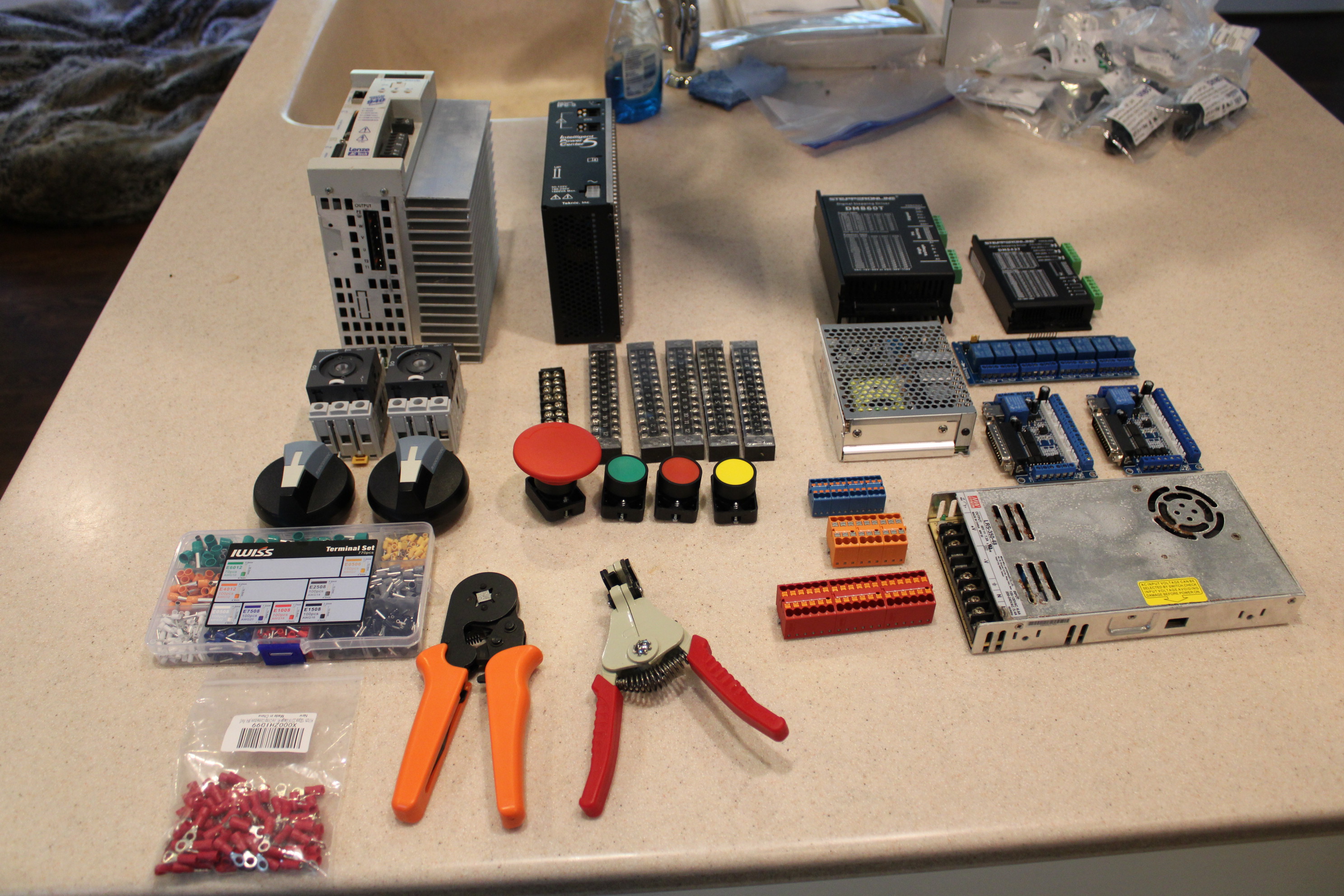
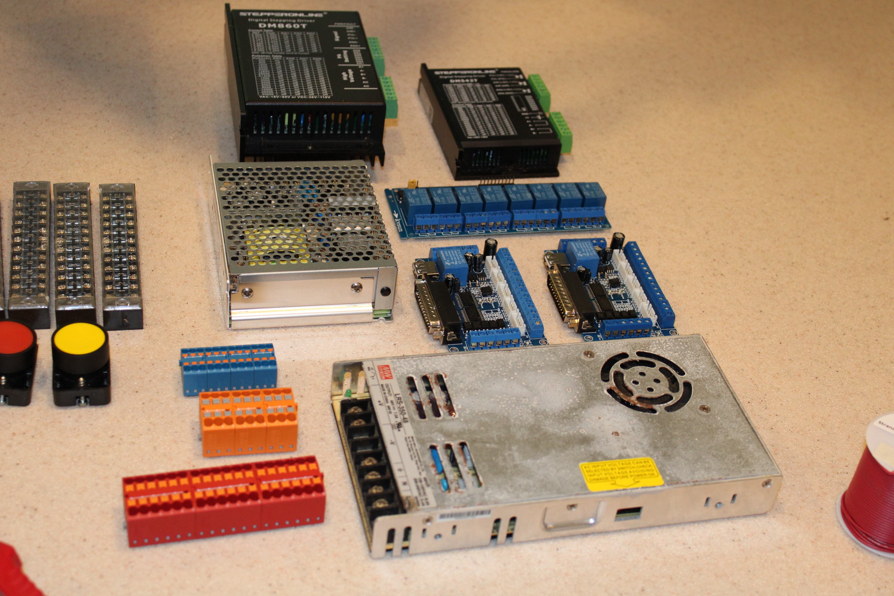
There will be 2 power supplies. One shows some corrosion because it spent some time powering an LED light above my old saltwater fish tank. That one is 48v and will run the 4th axis and tool changer stepper motors. The other is a 5, 12, and 24v power supply that will run most of the extras. Then there are 2 parallel port breakout boards which will handle the interface with the computer. Those should have more than enough IO for the machine. Above those is a relay board with 8 relays. That will control the draw bar, the tool changer air cylinder, spindle enable/disable, 4th axis brake, air blast solenoid, mist solenoid, and flood coolant pump. That leaves one more for something I am sure I am forgetting. Above those are the 2 stepper drives for the 4th axis and tool changer. At some point I might get some Clearpath servos to replace those steppers, but for now, I have steppers and I would like to put them to work. To the left of the 48v power supplies is the power distribution blocks. I found those on Mouser and they are inexpensive and pretty awesome in theory. They have adhesive backs to stick them to the electronics box surface and the big ones can handle insane power in theory (Something like 600v at 40 amps if I am remembering right. Don't quote me on that). Those will distribute the 120v line, the 240v line, and the multi voltage power supply.
UsA7PUC.jpg


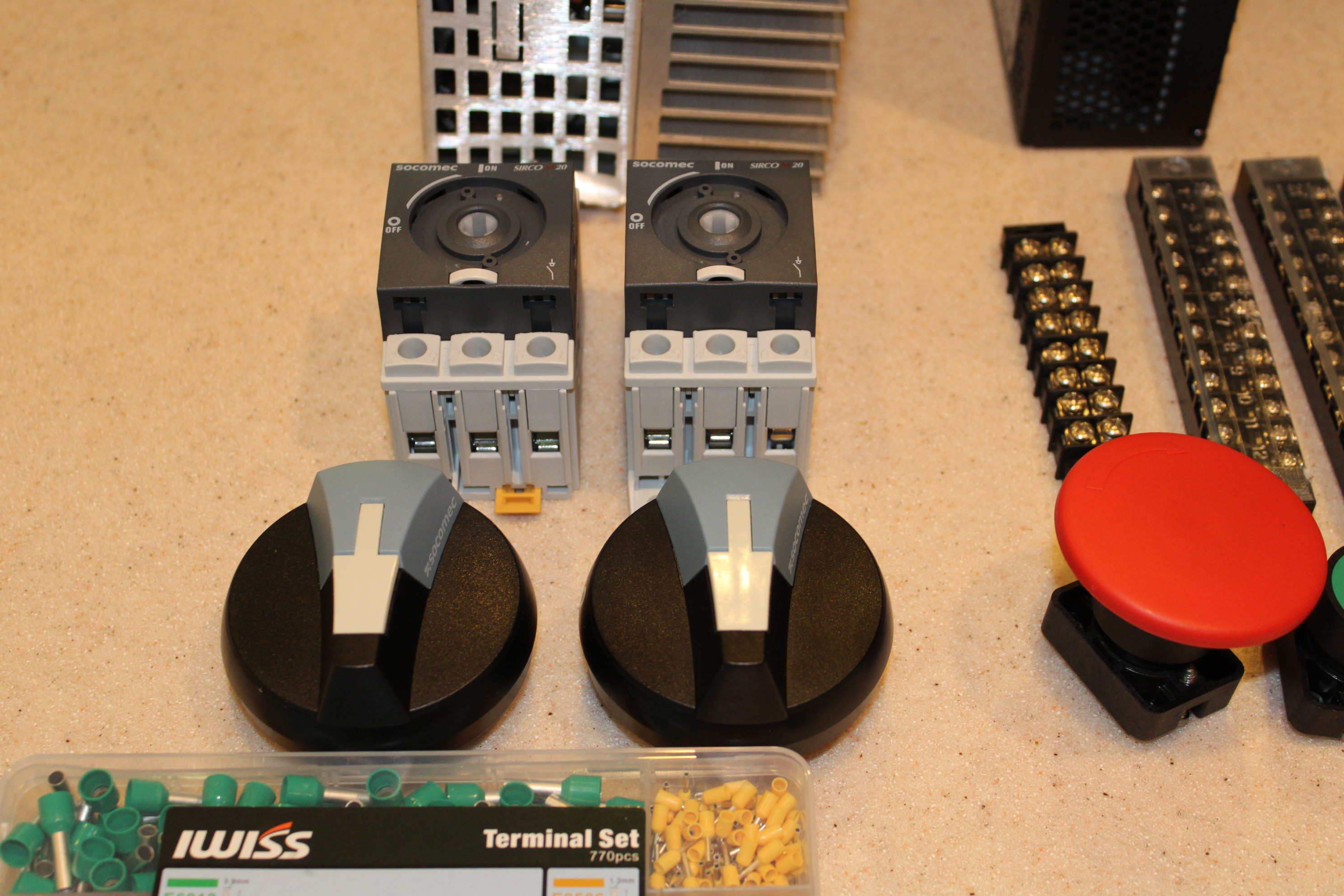
I picked up these disconnect switches from automation direct and I was thrown by the size of the knobs... I was not expecting them to be so massive. The switches are rated at 600v/20 amps each. One for the 120v line and the 240v line. I feel like there is a way to use just the 240v line and convert it to 120v inside the electronics box, but I couldn't figure that out with a few hours research, so I decided to just have 2 input lines.
ZrTKFof.jpg
 
I have a step down transformer I'm planning on using to convert 240v to 120v. You can also just break out one leg from the 240v but you will need the neutral so probably a 4 wire cable to run from the mains. I have both voltages running into my existing control box but it would be nicer to just have one plug.

Looks good, I've got to get going on my new electronics box now that I have my Y axis fixed (new ballscrew)

Cheers,

John
 
I feel like there is a way to use just the 240v line and convert it to 120v inside the electronics box,

In the US, 240V is two opposing phases (technically, "legs") of 120V each, and 120V is one of those phases against neutral instead of against the other phase. Your breaker box has both phases and your 120V circuits are some on one phase and some on the other.

Neutral is tied to ground at your main circuit box, but never use ground for neutral.

You can use a NEMA 14-30 straight or L14-30 twist lock to carry ground, neutral, and both phases. This requires running 3 conductor plus ground wire from the breaker to the outlet. This is a normal cable, nothing special. 10/3 W/G will I believe support 30A intermittent load which I would expect is fine; 8/3 W/G for continuous which I doubt you need on a mill that shipped to run off of 20A 120V intermittent or maybe even just 15A? You can ask an electrician, this is just my expectation not a qualified opinion

(Technically, this is single phase power, and the two legs are the same phase, inverted. The point is that while one leg is positive, the other leg is equally negative, and they swap roles 120 times per second, for complete cycles 60 times per second, which is our 60Hz main grid power.)

You could then use a single three phase e-stop for the two opposite hot wires and the neutral wire.
 
Looking great!

Your home utility is 240V where both legs are hot relative to ground. At the utility panel, a neutral wire is connected to earth ground and each leg of the 240V to neutral measures 120V. This is how all the outlets in your house work. The good news is this, if you bring the 240V into your cabinet with a neutral and ground wire, then you can tap one leg of the 240V and the neutral to get 120V. This is fine by NEC code. Try measuring it with a multimeter to prove it to yourself.

The only word of caution is that if you pull a lot of current (think 10A) on the 120V leg, then the current draw on your 240V will become imbalanced. This isn’t dangerous but if you protect your 240V line with a 20A breaker then it would trip sooner than expected.
 
Whoops! Someone replied at the same time as me.

Looking at your pictures, I see a lack of circuit protection. This is an extremely import part of building circuits and is required by code. Now I’m sure many here don’t build to code, but on a personal level you don't want you cabinet catching fire or damaging your electronics if something goes wrong.

Doing this stuff is part of my day job and I’m happy to help if you need thoughts on circuit breakers and wire sizing.
 
One more detail: if you have 240V options for power supplies, and you are running 240V anyway, use 240V everywhere you can. @macardoso 's point about unbalanced legs is one reason, but there is another.

W = V²/Ω = ΩA² and A=V/Ω so power increases as the square of the voltage but current linearly with voltage.

Power makes the machine go, and current heats the supply wire. So a (say) 2.2kW spindle, at (say) 85% efficiency, would consume about 2.6kW of electrical power. 2.6kW/240V = 10.8A which would dissipate 117W per Ω in the supply wiring. 2.6kW/120V = 22.6A which would dissipate 470W per Ω in the supply wiring, 4 times as much. You can probably see a reason why the rest of the world, more or less, uses 220-240V power. It requires less copper. Thicker copper, lower resistance per foot. That resistance has a smaller proportional loss at a higher voltage, all other things being equal.

Hope that's useful...
 
Back
Top