New PM-25MV Mill

One more detail: if you have 240V options for power supplies, and you are running 240V anyway, use 240V everywhere you can.

I forgot to mention that entirely! I use 240V for everything in my cabinet except for two small accessory outlets on the side of my panel for 120V devices like lamps or coolant pumps. It is just easier that way.

Also if you have a 200V class servo drive and you power it with 120V, you cannot get the rated speed on the motor (even if the drive is OK with 120V)
 
There hasn't been a ton of progress on the machine recently. I have it mostly reassembled in the new enclosure and I am working on getting everything wired up. I am going to redesign the motor mounts once more since I got larger bearings for the ballscrews and the current design won't work just right with them.

I managed to get the axis motors wired up and with the 75v power supply, I was able to achieve 600 IPM on the X and Y. The ballscrews didn't seem to like it though (old rolled ones, not the new ground ones) and I will probably drop that down to 300 or 400. The Z was stalling out around 350 and will be kept in the 250 range.

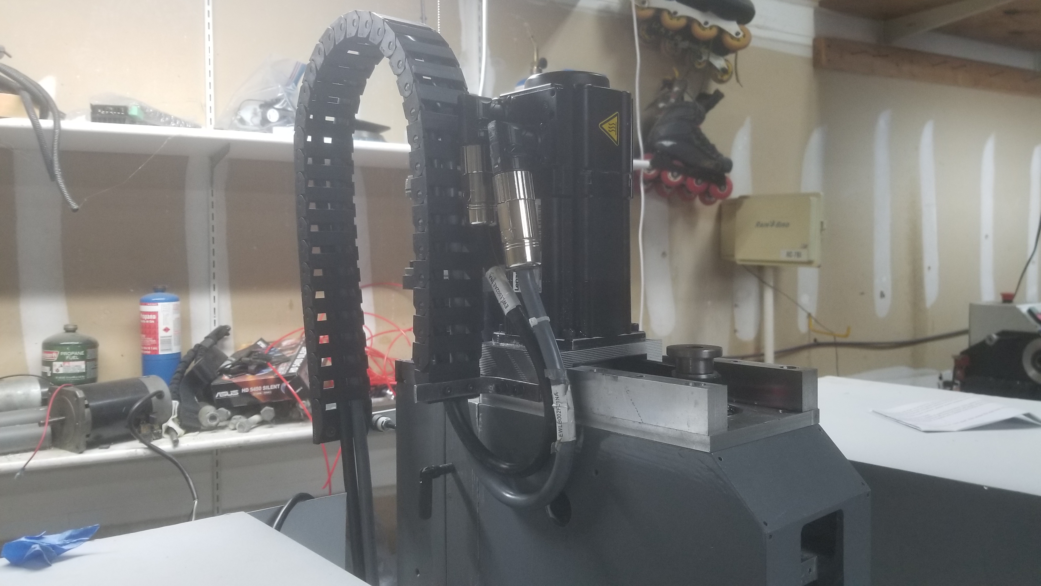
I got the cable carrier mounted on the Z and while I don't love how it is on there, I don't see another decent alternative. The spindle motor cables are so beefy that tighter loops just aren't going to happen and when spinning the connectors around the other way, the cable chain would need to be mounted so high it was ridiculous.

I apologize for the picture quality. There is dust under the glass in my phones camera so most of the pictures look a little hazy now. I had to take apart the connectors to get the cables to fit through the carrier, so it will be a while before I change anything on it again. I will say though that those M23 connectors are much nicer than any of the other ones I have used.
38BMZGm.jpg


Macardoso, I have overlooked circuit protection. I have always assumed that the circuit breaker on the house and the internal fuses on the nicer electronics were enough. In the past, none of my electronics were worth enough to worry about adding extra protection, but now some of them are. Would would you recommend adding for further protection? I would like to at the very least protect the clearpath motors, the clearpath power supply, the spindle drive, and the control computer. I am currently using 12 AWG cable to connect the wall power to the electronics box, then I mostly stick to 14 AWG for anything carrying power, or whatever the specific manufacturer recommended.

Also, it has probably been a while, but you helped me set up the spindle drive when it arrived and we covered the 120v vs 240v performance quite a bit. I am thinking for my next machine (or next iteration of this one) I will try to get everything I can on 240v.
 
So, circuit protection is mostly to protect the wires, not so much your components. You have to imagine that if you were to short two terminals anywhere in your cabinet, where are wires going to melt. Typically you'll have one big main breaker in your cabinet (that should trip before the breaker in your home's breaker box) and several smaller breakers/fuses for individual components. You CAN get around using breakers if you run wire large enough to carry the entire panel's Full Load Amps (protected by your house's breaker), however this can get expensive and is not necessary.

At 12AWG, you need to make sure your house breaker is not more than 25A. Again this is all to make sure your panel doesn't start a fire or melt your wires.

If a component is going to fail, it is unlikely that your upstream protection is going to help save that device at all, however it can protect upstream components.

If you send me a sketch of your circuit, I'd be happy to help recommend where you should have breakers or fuses.


Awesome work as usual! You keep me motivated to keep working on mine!
 
I'm a programmer, not an electrical engineer, so I write with trepidation, but... When it comes to circuit protection the question is which risks to what components are you protecting against. TL;DR: a circuit breaker or fuse protects against things melting when there is a downstream short circuit or otherwise drawing enough current to melt wires upstream. Note that this is not particularly effective for protecting downstream components; there's not much a circuit breaker will do to protect your clearpath motors. For that, you need transient voltage suppression.

There are two classes of circuit protection, basically: over current and over voltage. Circuit breakers are over current protection. Excessive current produces excessive heat, and over current protection protects against effects of heat, up to and including fire. Your home circuit breaker protects the wires in the walls. If you have thin wires connected to the outlet at a gauge that might be damaged or catch fire before tripping your home circuit breaker, they should be behind a smaller over current protection device (fuse or circuit breaker) so that there is a breaker that trips before those wires melt or catch fire.

A GFCI is basically a very sensitive over current protection device that trips if it measures any current to ground, as personal protection against electrocution hazards.

A circuit breaker basically does nothing for over voltage protection (except in as much as sustained over voltage causes over current), and to protect your motors you want over voltage protection as well as over current protection.

There are basically three ways to protect against over voltage: shunt it through a temporary intentional short circuit (a "crow bar"), do something to limit exposure of a sensitive circuit component to a high voltage by filtering it, or sense and interrupt the circuit (effectively a circuit breaker, but not what we normally mean by "circuit breaker"). You probably care only about the first two. (AFCIs are kind of a special kind of filter-triggered circuit breaker that is tuned to a particular kind of noise associated with arcs, which is why they can be annoying with physically commutated motors, which can be annoying in the home shop.)

The surge suppressors you can buy cheaply use devices called metal oxide varistors (MOVs) which are basically insulators at normal voltage but conductors at high voltage. These are shunt devices. They are available with different voltages and energy dissipation capacity, and usually fail short circuit (unless they are blown to bits), so they need a circuit breaker or fuse "upstream" to protect against over current if they fail short. The goal here is to protect equipment from a large increase in voltage. My understanding is that typically heavier-duty (can absorb more energy) MOVs are less sensitive, so it's not that unusual to have a whole-house surge suppressor installed on the main panel, and individual surge suppressors on sensitive equipment. At DC component levels, and especially at signal levels, TVS (transient voltage suppression) diodes are common shunt devices. They are available with a wide range of "breakdown voltages" at which they start to meaningfully conduct. They provide a similar benefit, and I think typically respond faster than MOVs, but carry less energy. (They are available in bidirectional versions that are appropriate for AC signals as well as unidirectional versions appropriate for DC signals.)

The line between filtering and shunting can be blurry. A resistor and capacitor can be seen as shunting a transient spike or filtering a high frequency signal, and it's really the same thing. But an inductive filter in line (including ferrite cores) is only a filter and not a shunt. An inductive filter limits the rate of change of a signal going through it; you can think of change of magnetic field having inertia. So an inductive filter can both protect against noise and relatively low, short voltage transients, and so is mostly useful for cleaning signals of signal-level transients rather than damaging voltages, as I understand it. @macardoso has been using ferrite beads for signal cleaning recently. ☺

I don't know if that's interesting or useful. Others here can chime in with more informed help than I can.
 
mcdanlj- Very helpful in my understanding of this!
Robert
 
I'm a programmer, not an electrical engineer, so I write with trepidation, but... When it comes to circuit protection the question is which risks to what components are you protecting against.

Awesome explanation, thank you! From my experience in the industrial automation sector, there typically is not any surge protection installed on equipment except what is already present in the devices being installed. Overcurrent protection is required by code (NEC, IEC, etc.) and is installed everywhere. I have installed surge protection on a small number of panels, but these were specialty applications which were very different from your average factory.

If your concern is about the Clearpath motors, it is likely that the only thing which will be damaged in the event of a lightning strike would be your power supply. I find it unlikely the motors would sustain damage (power supplies typically protect the output in the event of failure). Lightning strike is quite rare so I wouldn't worry yourself too much!

-Mike
 
From my experience in the industrial automation sector, there typically is not any surge protection installed on equipment except what is already present in the devices being installed.

I think most industrial automation would have on-site transformers down to 480/240V with the downstream not particularly exposed to risk of lightning, and the transformer is a massive inductive filter. Whereas practically all residential power shares a stepdown transformer between multiple houses and in some places that's above-ground, so more exposed. I don't know, though; does that make sense?

Lightning strike is quite rare so I wouldn't worry yourself too much!

Down here in our part of NC (@shooter123456 and I live near each other) there's a lot of overhead last-mile power, and anecdotally the incidence of lightning damage seems higher here than in MN and WI where I grew up, where most of the 240V power distribution is buried. I don't know whether that's supported by data and honestly don't know where I would look. My current neighborhood has buried kV-range (I think) distribution, but my previous neighborhood had 240V on poles everywhere and power wasn't very clean. I think that a few decades ago it was substantially more expensive to bury cable in the heavy clay here than in the loam and gravel I grew up with. Even so, my parents in WI, with all below-ground feed from their upstream transformer to any of the houses it feeds, have had two lightning events that have damaged electronics over the past two decades, in both cases from lightning strikes on their property. There's anecdata for you! ;)

I find it unlikely the motors would sustain damage (power supplies typically protect the output in the event of failure)

I certainly agree, unlikely. In the realm of unlikely, I would assume that the first thing to go would be the encoders on the motors, not the coils in the motors.

Are the power supplies fully isolated?

Anyway, a surge suppressor can absorb only so much energy, but it's relatively cheap insurance that protects against at least some borderline cases. If you are in an older neighborhood with overhead power, I think it's worth it. (I have whole-house and individual surge suppressors, even with underground delivery from the transformer maybe 50 feet away, but that's probably overkill.)
 
Well, I've never heard of anyone who has had as many issues with lightning as you, but I guess if I had, I'd be worried about surge protection too! :D

Thanks for sharing, I definitely learned something.
 
Here in the CLT all the lines are overhead and we have some bad electrical storms. It is common to have strikes with 1/2 mile from my house. I am surprised I have not had a major issue yet.
Robert
 
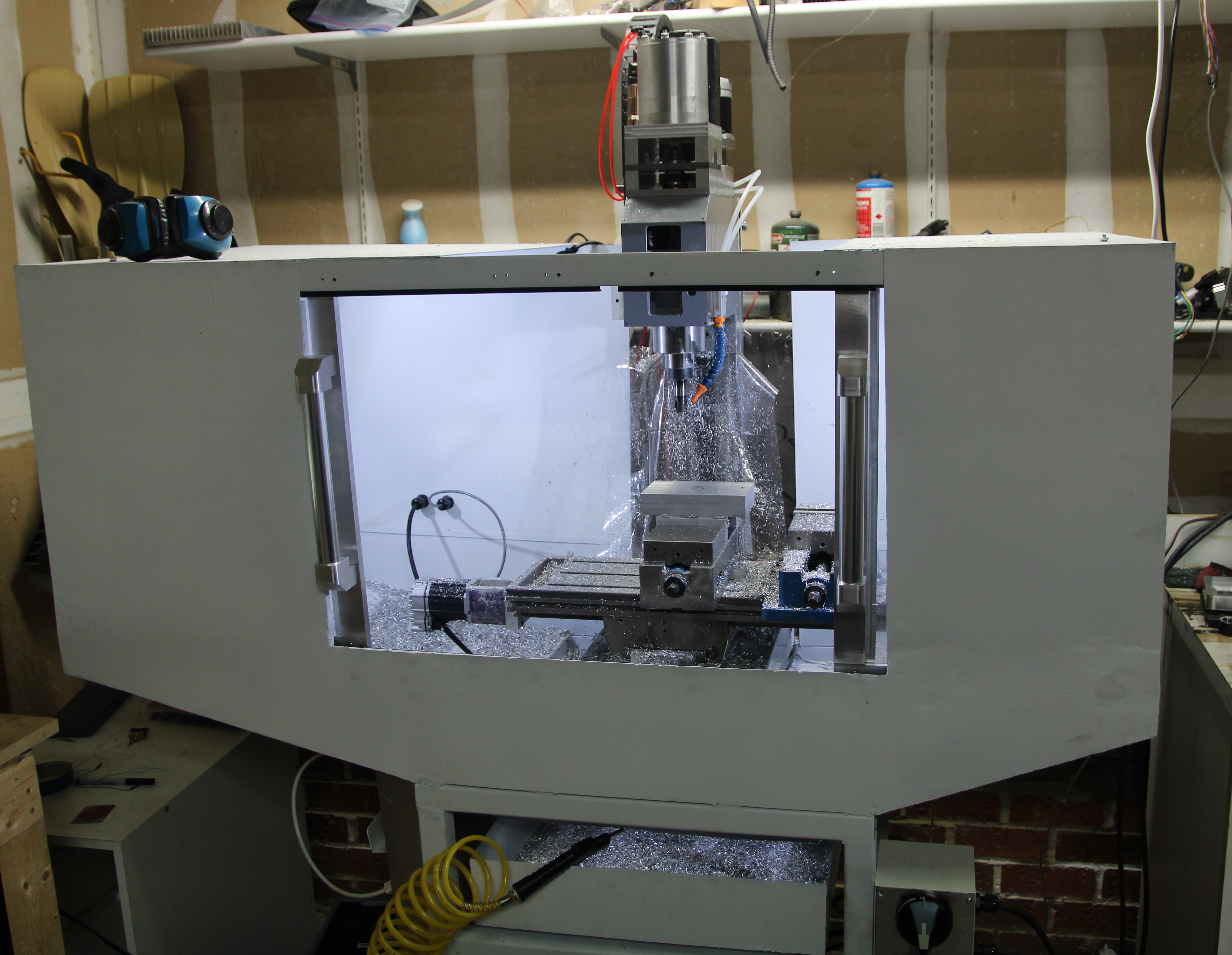
I have made some progress recently! Things are coming along. The machine is all wired up, everything is back together, and it is making chips again. There is still plenty of work to be done, as usual, but it is alive and kicking.

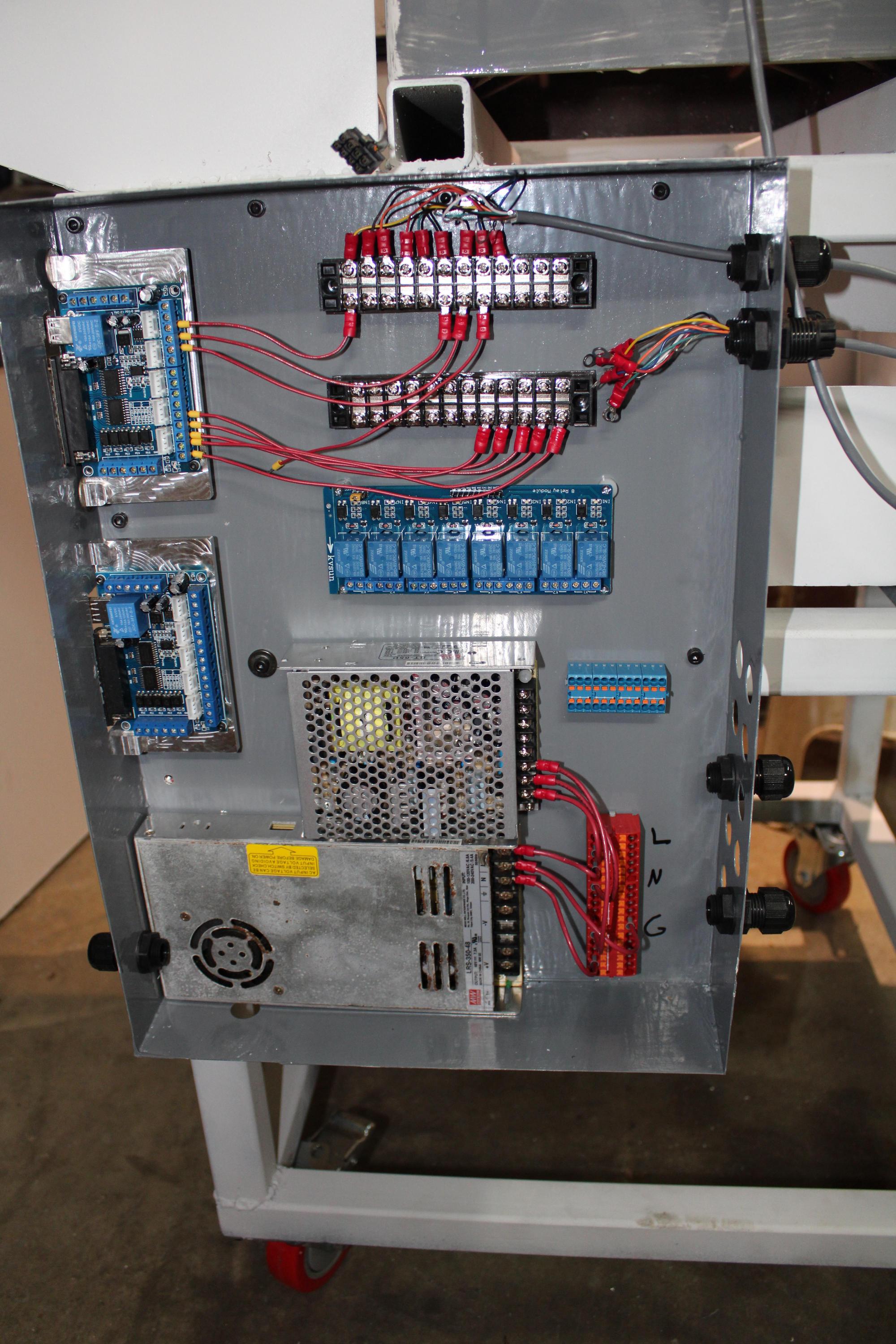
Here is a quick look of the electronics box while it was still being wired up and still looked somewhat clean. The spindle drive and the servo power supply are both mounted outside the control box. The large 48v power supply will be used to power the steppers for the tool changer and 4th axis. I have not decided yet how I will control the tool changer, but I added the second breakout board for the extra IO just in case I wanted to run it directly from the control computer instead of going through a separate micro controller.

PEgeXva.jpg


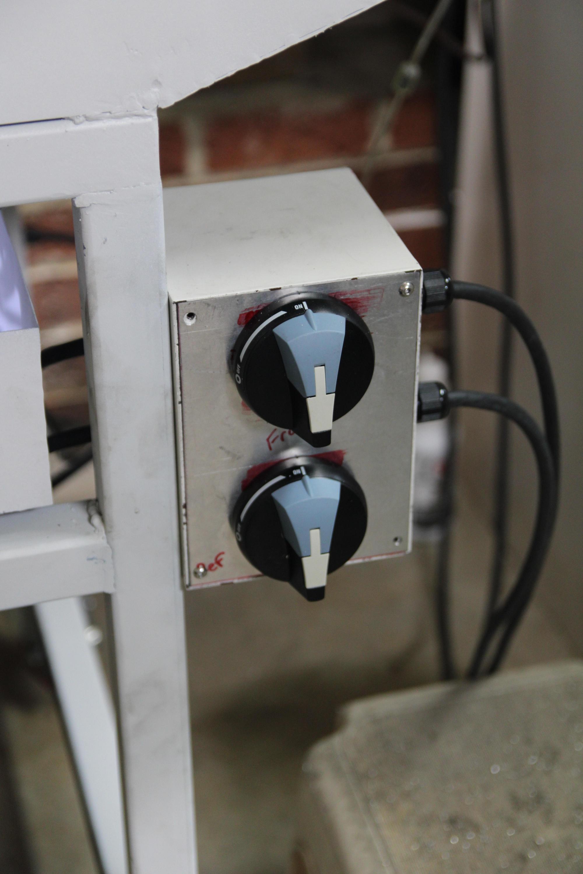
Here is the repurposed spindle control box that came mounted on the head originally. The top switch is the 240v input and the bottom is the 120v input. It works just fine and I like being able to cut power easily with the switches.

Os0s1zF.jpg


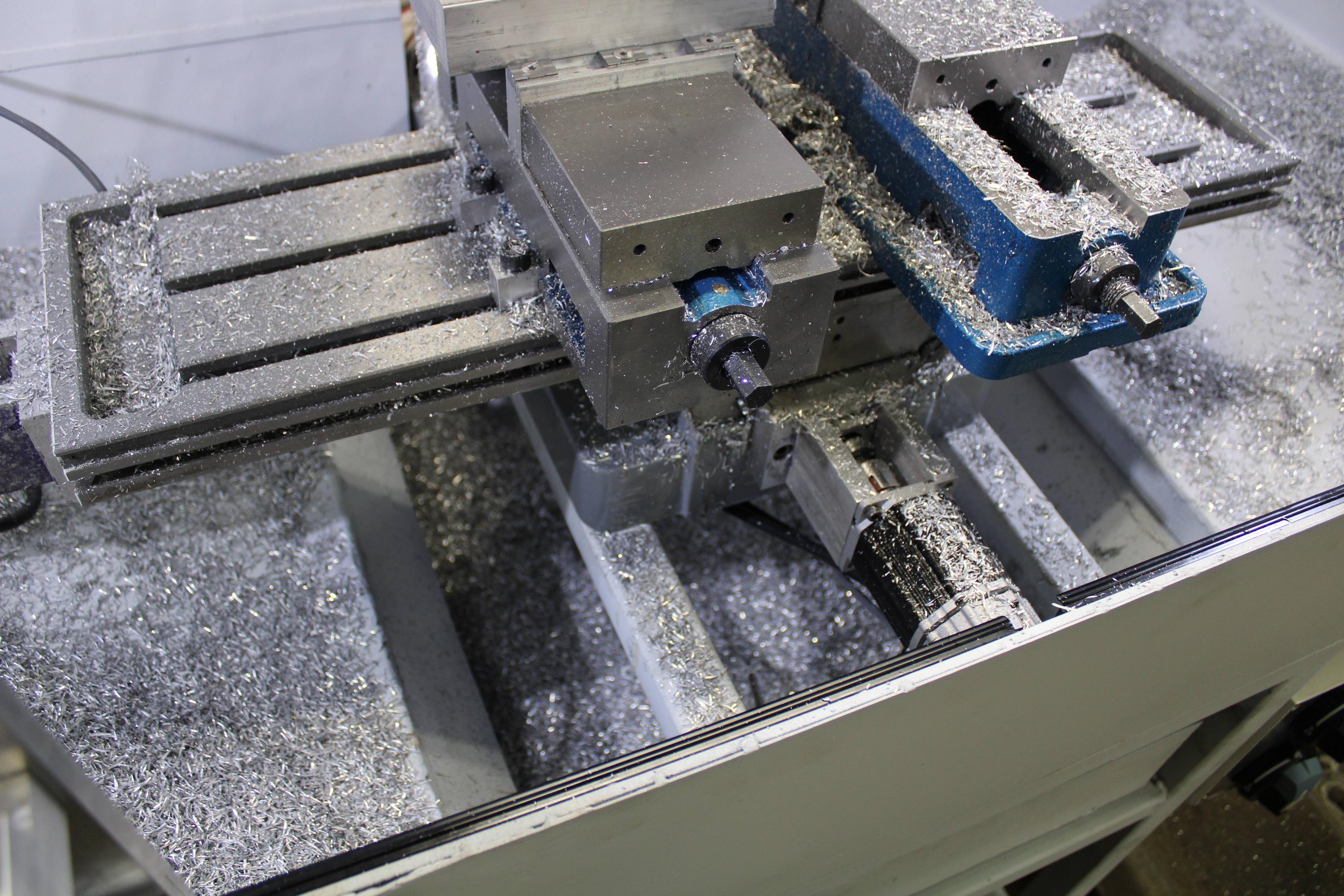
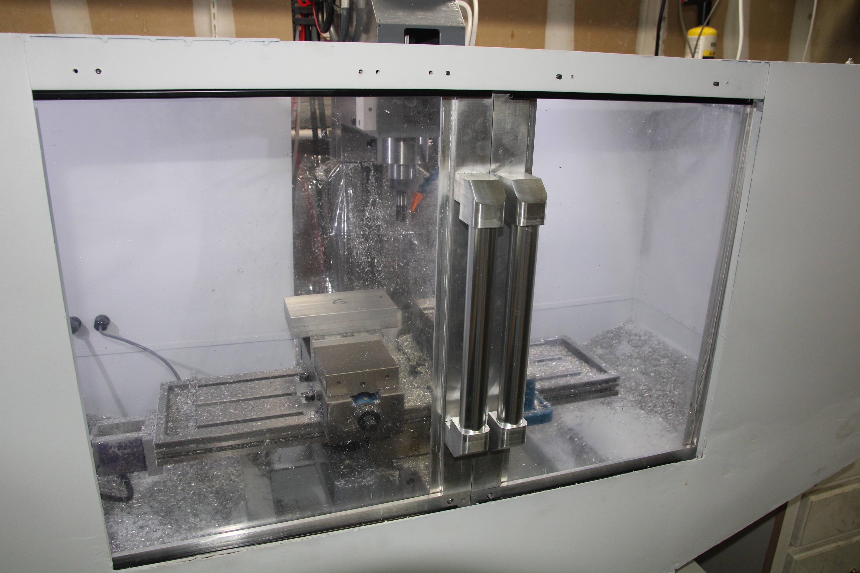
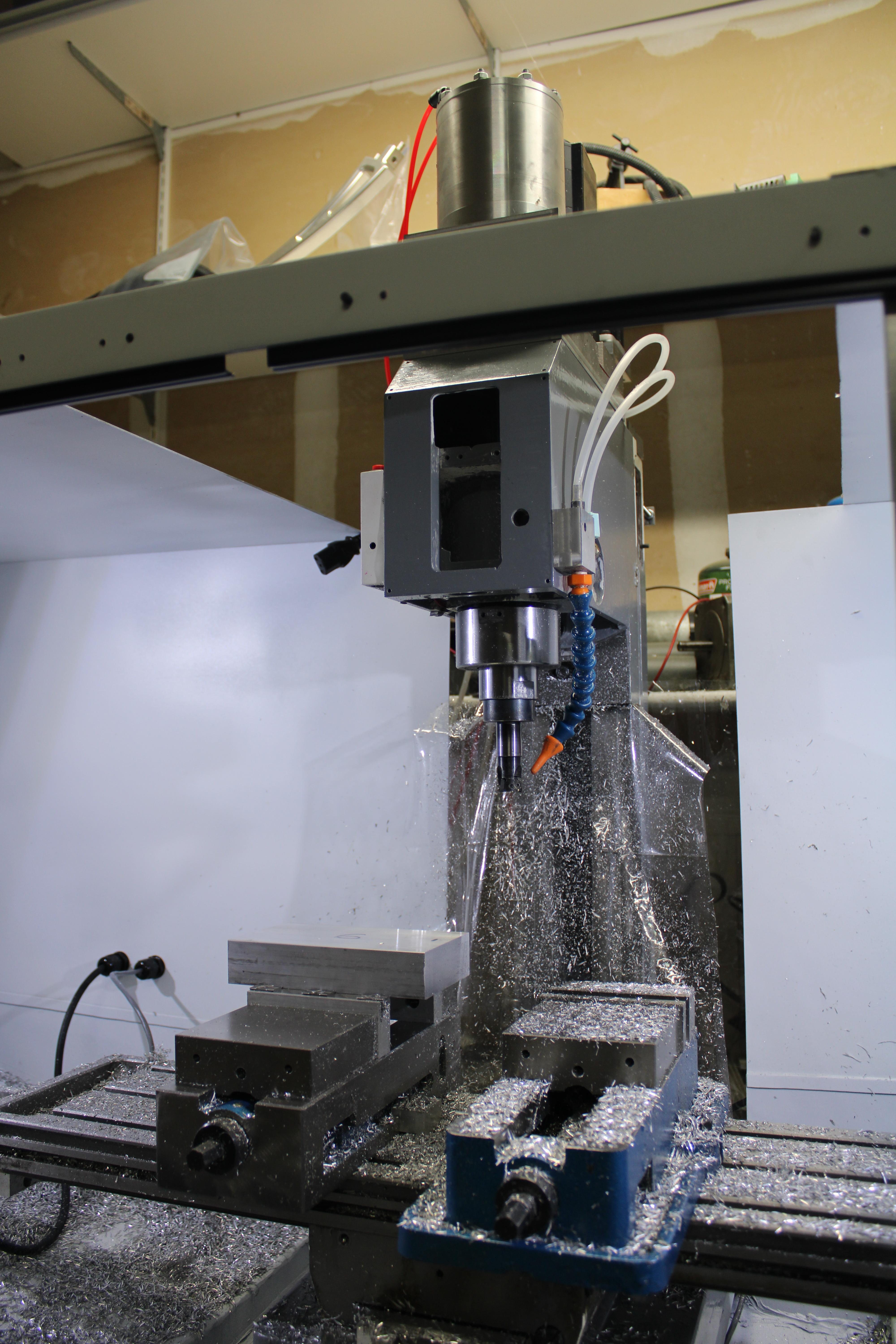
The chip containment on the enclosure is excellent. The chip chute and chip tray are working exactly as I had hoped. The only place I have chips escaping is occasionally out the top. It isn't enough for me to worry about it though, so for now I won't make any changes to that. Here is a top down look at that.

2gSMsde.jpg


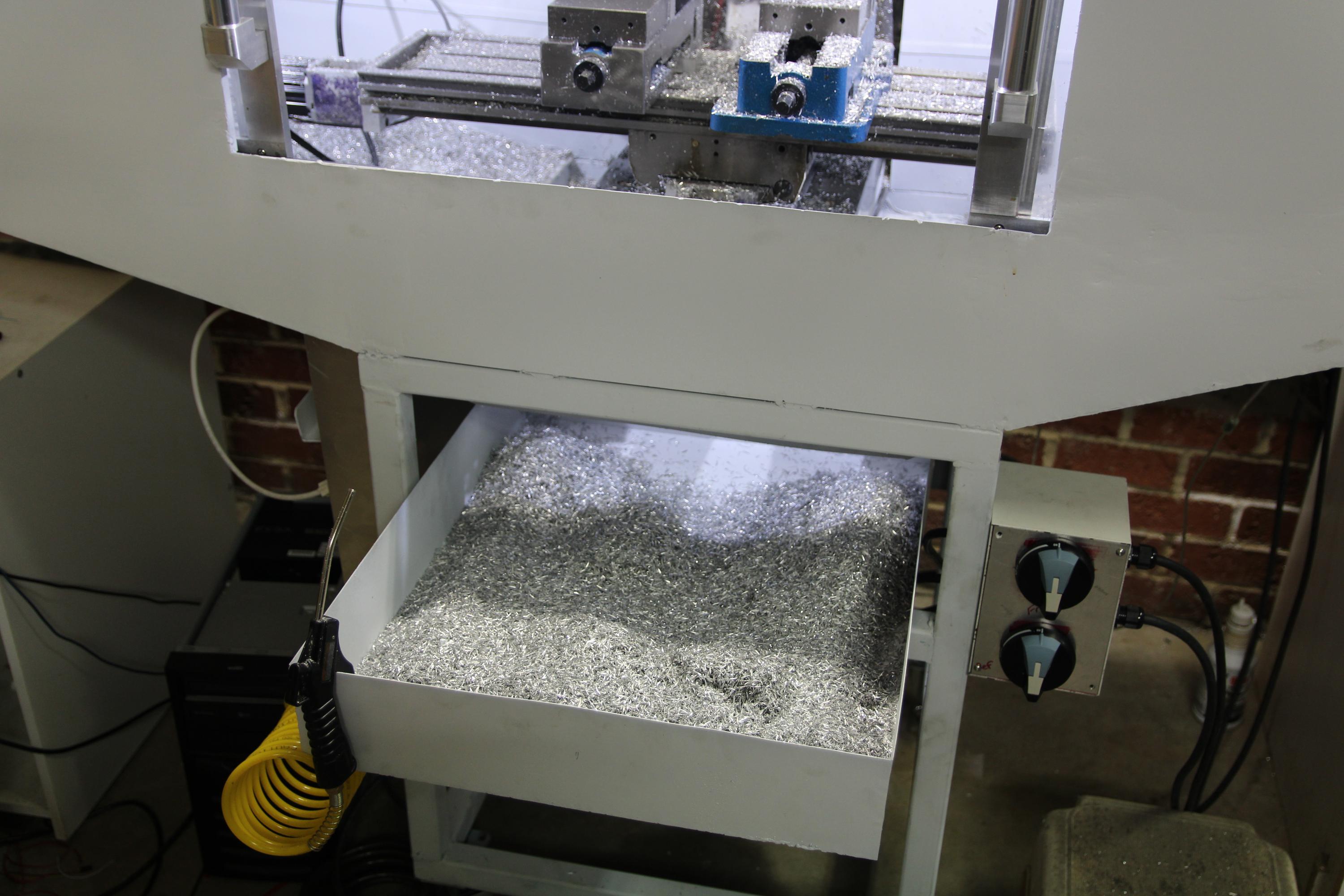
Chip tray full of chips on slides. Just slide it out and scoop the chips into a bin. I still want a chip auger though...
xdocWql.jpg


Here are a few more pictures.
uBTcRdk.jpg


pHAmLIO.jpg


xQwlapX.jpg


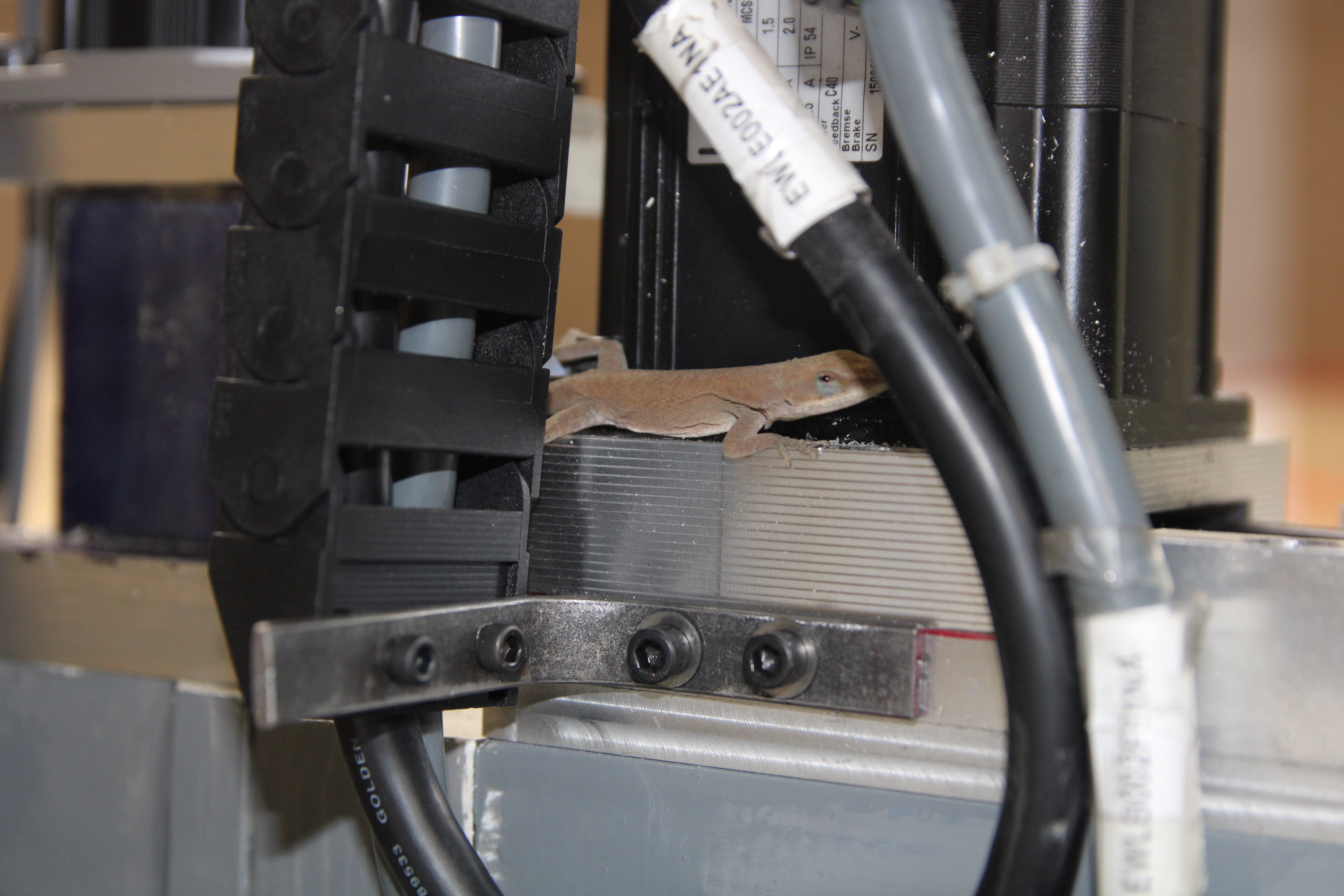
I also had a shop visitor one day. He showed up on a particularly cold day, probably just looking for somewhere warm. I wasn't running the machine that day so luckily, he did not get hurt. I have not seen him since though...
PAxpOdM.jpg


I am working on making new X, Y, and Z motor mounts now so I can mount the new ground ballscrews. I got some larger bearings and the new mounts will protect the motors and couplers.

I will also be adding some circuit protection just to be on the safe side. I think the enclosure could use some stiffening, so I will be welding some more next time the machine is out. Overall, I am happy with how it is working.
 
Back
Top