- Joined
- Sep 22, 2021
- Messages
- 115
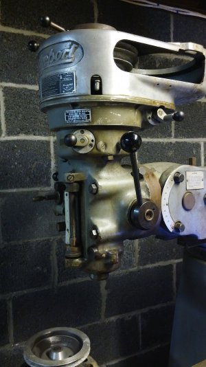
This video shows the head off to the side so I had lots of room to clean. I explain the Ram being stuck/seized up as well as the excessive backlash on the Y-axis screw. That's it for today.

This video shows the head off to the side so I had lots of room to clean. I explain the Ram being stuck/seized up as well as the excessive backlash on the Y-axis screw. That's it for today.
")
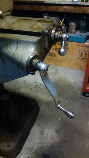
Thanks for your idea, Norseman, I'll give it a try and I'll let you know how it went.PB Blaster is your friend fer gittin the ram loosened, up spray and tap the ram with a dead blow hammer and rock the drive handle spray let it sit fer a while repeat till it works loose ..........................BE PATIENT and persistant ....................
OH yeah pull the lock bolts out and spray the PB in them too.................