Old Bridgeport Gets New Lease On LIFE

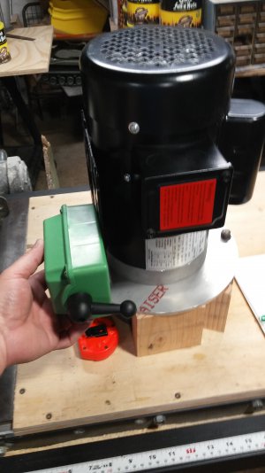
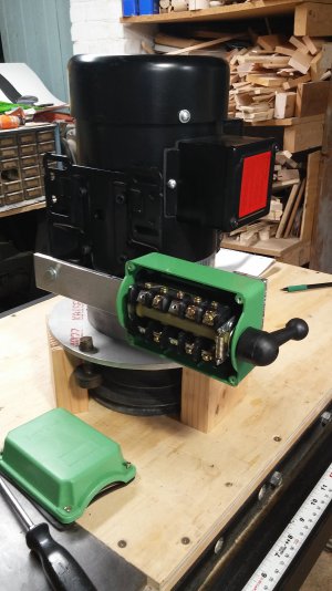
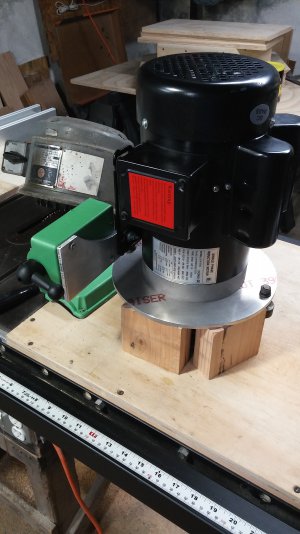
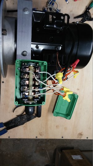
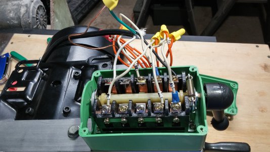
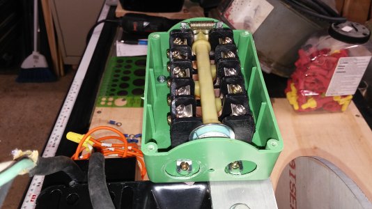
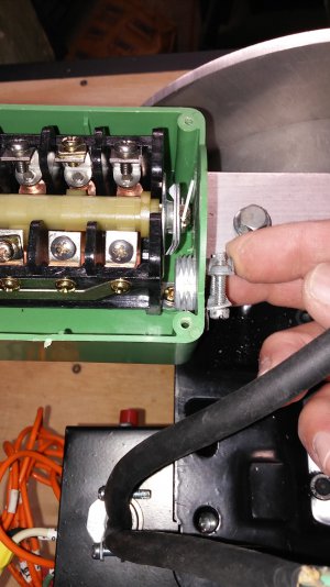
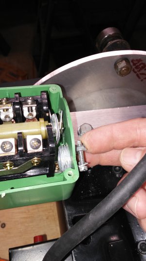
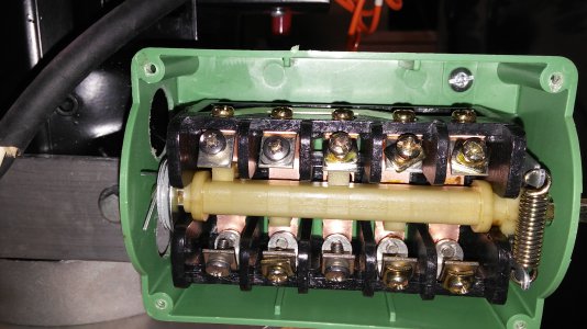
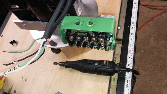
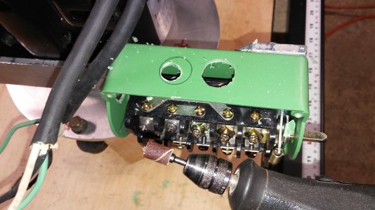
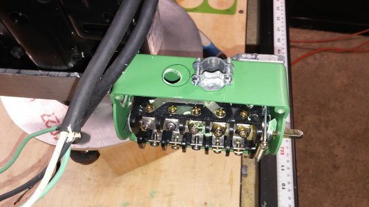
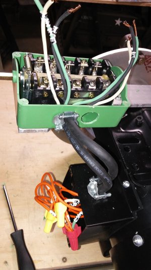
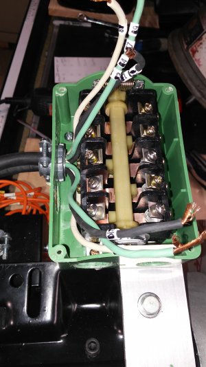
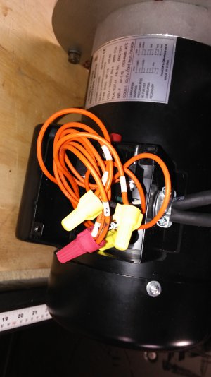
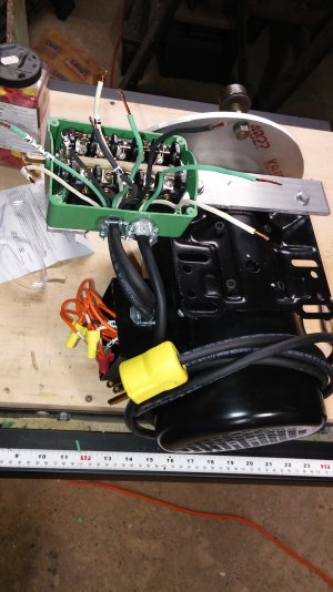
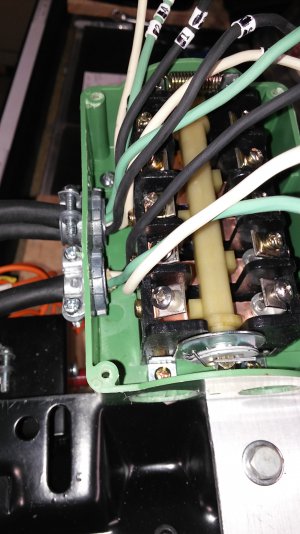
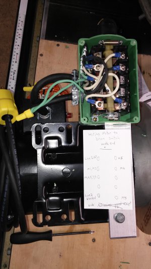
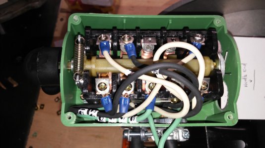
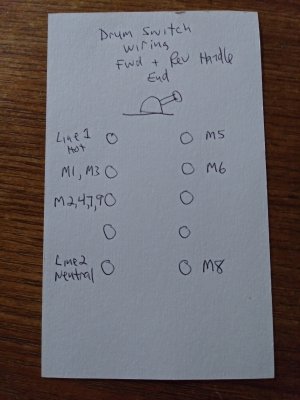
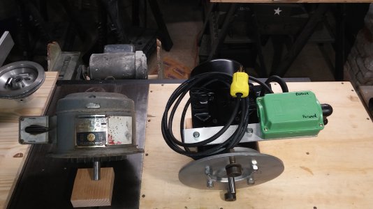
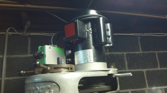
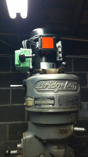
Next, I made a mounting bracket for the Drum Switch and I mounted it on the motor. The switch mount was made from a scrap piece from the new motor mounting plate (sorry, no photo, but I will share an image that shows it). The switch is closer to the front of the machine than the original that was built into the BP Motor, but the switch isn't in the way of the brake handle. Then I reached out to Ulma Doctor. for his help wiring the switch.
 
Ulma Doctor has a video on YouTube showing the exact same switch I got for this project and he didn't show the wiring diagram on YT, but in the video description, he said for a detailed wiring diagram go to hobbymachinist.com. I credit the good Dr. for joining this fine group of like minded guys who have been a great help to me and this project.

Here's a link to Ulma Doctors project which got me to join Hobby Machinist: https://www.hobby-machinist.com/thr...-switch-and-drum-switch-retrofit.85448/page-3
 
Last edited:
Enough talk, here's what was done. First, the switch was mounted. OK, so as promised, take a close look at the 2nd & 3rd images to see the switch bracket I made. Next, using the wiring diagram molded onto the inside of the switch cover as well as the plate on the motor, I tried to test wire the motor on the bench before doing the actual Finish wiring and installing the motor on the BP. Here are a couple of wire salad photos of my feeble attempt to wire the switch to no avail. Then after a couple of days, Ulma Doctor drew a simple wiring diagram for all of us Non-electricians to understand. But still, nothing because one of the wires was omitted from the drawing.
 

Attachments

  • 20210921_191433.jpg
    20210921_191433.jpg
    1.3 MB · Views: 17
  • 20210922_125448.jpg
    20210922_125448.jpg
    1.5 MB · Views: 13
  • 20210922_125507.jpg
    20210922_125507.jpg
    1.5 MB · Views: 11
  • 20210926_123400.jpg
    20210926_123400.jpg
    2.2 MB · Views: 10
  • 20210926_123433_HDR.jpg
    20210926_123433_HDR.jpg
    2.3 MB · Views: 10
Then, markba633csi joined the conversation with the correct placement of the last wire, and Sucess, the Motor came to LIFE in both Forward and Reverse. Now, since this is a single phase motor, the BP brake must be used to completely stop the motor before reversing the motor's direction.

Next, the finish wiring begins!!!!!!!!!!!!!!!!!!
 
I bought this drum switch on E-bay, and yes, it's Chinese, but it fit the budget. The switch is said to be weather resistant thus the location chosen for the wires to enter the switch should face toward the ground if used outdoors. But, as you will see, the wire entry location doesn't allow much room for the wire. Hey, it's Chinese, what can I say? But no worries, the side has more room for my application, so here come two new holes.

OK, so the last image shows two wires entering the same wire clamp. This is most likely a BIG No-No and not what an Electrician would ever do. To be honest, I was going to use a flexible waterproof conduit between the switch & motor to pull the wires through, but due to the close proximity between the switch & motor, it would have kinked and wouldn't have worked.

Oh well, it's bag enough I'm using two pieces of the same wire coming out of the motor, but as you will see, I clearly marked each wire.
 

Attachments

  • 20210929_095253.jpg
    20210929_095253.jpg
    2.4 MB · Views: 9
  • 20210929_095352.jpg
    20210929_095352.jpg
    1.4 MB · Views: 8
  • 20210929_095401.jpg
    20210929_095401.jpg
    1.4 MB · Views: 8
  • 20210929_095637.jpg
    20210929_095637.jpg
    2.5 MB · Views: 7
  • 20210929_100121.jpg
    20210929_100121.jpg
    2.3 MB · Views: 8
  • 20210929_100227.jpg
    20210929_100227.jpg
    2.2 MB · Views: 8
  • 20210929_100322.jpg
    20210929_100322.jpg
    2.2 MB · Views: 8
  • 20210929_101556.jpg
    20210929_101556.jpg
    1.1 MB · Views: 8
Next comes the power cord into the switch. Then the wiring is completed and tested. The last image is a redrawn wire diagram.
 

Attachments

  • 20210929_101606.jpg
    20210929_101606.jpg
    1,013.5 KB · Views: 9
  • 20210929_095232.jpg
    20210929_095232.jpg
    1.2 MB · Views: 7
  • 20210929_103229.jpg
    20210929_103229.jpg
    1.5 MB · Views: 7
  • 20210929_103344.jpg
    20210929_103344.jpg
    1.3 MB · Views: 7
  • 20210929_104953.jpg
    20210929_104953.jpg
    1.3 MB · Views: 5
  • 20210929_105000.jpg
    20210929_105000.jpg
    1.3 MB · Views: 6
  • 20211011_162627.jpg
    20211011_162627.jpg
    3.4 MB · Views: 7
The original BP motor and the new single phase motor are shown side by side.
 

Attachments

  • 20210929_110330.jpg
    20210929_110330.jpg
    2 MB · Views: 7
Now a short benchtop motor test video before heading out to the garage to install the new motor.
 
Before I mounted the new motor on the old BP, I made the new motor lock handles out of 1/2 inch aluminum rod stock on the 7"x10" HFL (Harbor Freight Lathe). I drilled & tapped each end 1/4-20 and on one end, I used a dab of blue Locktite to secure a short piece of threaded rod. I will do the same to the exposed ends of the handles when I get the 1 inch black plastic knobs.

Being a Machinist, I never took the time to read through the owner's manual for the HF lathe. Then one day I was curious to know if collets could be used with this lathe. I removed the 3 jaw chuck and I was pleasantly surprised to find that the spindle has an MT1 taper. So, I got a set of 8 collets off of E-bay from 1/8" up to 3/4." I also made my own faceplate that attaches to the 3 Jaw chuck with the jaws removed. A piece of 1/2-13 threaded rod holds it in place.
 

Attachments

  • 20210929_120806.jpg
    20210929_120806.jpg
    2.5 MB · Views: 8
  • 20210929_120816.jpg
    20210929_120816.jpg
    3 MB · Views: 7
  • 20210929_121012_HDR.jpg
    20210929_121012_HDR.jpg
    2.4 MB · Views: 6
  • 20210929_125024.jpg
    20210929_125024.jpg
    978.6 KB · Views: 6
  • 20210929_125123.jpg
    20210929_125123.jpg
    1.9 MB · Views: 10
Last edited:
Finally, the moment I've waited for, seeing & hearing my Old BP coming to life, and listening to hear if the spindle bearings are good, or bad. I was very happy the spindle of my $900 dollar BP is OK. I think the single phase motor makes more noise than the BP motor, but it's a small price to pay to add a BP to my Home Shop. Sorry, the fluorescent lighting makes the photos look strange.
 

Attachments

  • 20210929_192717.jpg
    20210929_192717.jpg
    2 MB · Views: 9
  • 20210929_193937.jpg
    20210929_193937.jpg
    2 MB · Views: 12
  • 20210929_194417.jpg
    20210929_194417.jpg
    1.3 MB · Views: 14
Back
Top