Hi Folks,
I folks, I purchased a PM940M CNC a few years ago. I was so naive I missed a bunch of things at the beginning. However, I know a lot about the z-axis gib and ways now and am still trying to work out some fixes. Some folks get a better machine than mine..... PM is good about helping but somethings they do not have control over. Lots of things were wrong with my machine. Yes, it nods too. We are all seduced by the large working ranges of this machine, but I think this is also part of its problems. At this stage it if had not been so much trouble to get into my basement (basically had to disassemble the table, stand and take the CNC electronics and enclosure off to move it in in pieces) I would get something else. I may yet, but I am still using it.
Clamp the head to the ways before knocking the gib out from the bottom. Blocking is a safety factor, but once the gib is out the head can roll, yaw and pitch a lot. I don't think it will fall off of the ways, but it is close. I have had my gib out many times and have order materials to make my own ... maybe. (PM, Matt, offered to make a new one for me, so I cannot fault them.) I have a very large C clamp for holding the head to the column. However, probably some bar clamp would work. I did knock the pain off of the soft bondo they cover the whole thing in. (The cast iron is not very good, rather sandy. If you think other wise just try tapping a hole in the column. You can do it but I recommend you use a drill that is considerably smaller than the normal steel tap. I think this bad material is why some of the smaller screws in my machine are so loose. The screw threads are smaller than the grains of the cast iron!)
If you loosen both ends of the gib screws and then crank the head up the gib will slide down and get tighter. If you then crank it down the gib sometimes stays high and starts to come out the top. Probably depends on number of factors, but that is what mind does. Anyway, this is one way to get the gib loose. Then insert a rod up from the bottom and push the gib out. A tap may be needed, but by clamping the head to the ways the gib is no longer holding things.
As far as the clamps I used them to keep my head from falling for a while. However, when I took the gib out, it was very beat up from the screw ends. Some pretty deep holes...and they were not all in one place like they should be if the gib was not moving around!
Fundamentally the machine is designed wrong or under designed for the head weight or the head is just too heavy. Then there is the poor QC in China. The 904M is head is heavy. Via my measurements and others it is between 250 and 300 pounds. The the column for the vertical ways is heavy, but too light weight for this head.
At first I thought the ways were not uniformly cut the length of the column so that the way spacing varied as you go up and down. This maybe still the case in my machine as I still need to precisely measure across the width of the ways. Precise means 0.001" or less across the way width as one goes up and down. This is hard to measure once the head and motor are on unless you have special tools to fit behind them. I believe that mine varies more than this. What one really wants to do is measure this distance just behind the motor as the motor is moved up and down. Hence, my next paragraph.
The second issue is due to the strength and design of the column. The concept model is as follows: I now am thinking that due to the head forces, the ways actually move towards each other in the center region where the ball nut support passes through the U shape of the column. At the top and bottom, where there is no travel, the column has the steel in between the ways so is stronger. So if the U shape bows together at the ways due to the head weight then the ways/gib are looser in the middle that at the top or bottom. On my CNC machine the little stepper's powered off cogging and the gib friction will hold the head up when at the top and bottom, but the whole thing walks down when in the middle. (Not good when the power goes off. The stepper is strong enough to hold when the power is on, but if the gib is too tight then steps are missed on the way up... too loose and maybe there are extra steps on the way down... Not good for a CNC machine. ) So this behavior is because the gibs are adjusted to be tight at the top or bottom. In the middle they are loose and the head also nods!!!! So far the only solution that I possible have is to reduce the weight or to support it some other way. Currently, I am thinking that the ways bow inward about 0.003-0.005 in the center of the distance between the U shape becoming a box, at the ends. This represents tightening the giby by a lot. The head saddle, contacts the ways at the top and the bottom as it tries to nod, rotates due to the torque. Hence, the bottom rests against the column and is ok, but the top pulls on the ways causing the ways to deflect towards each other. There is a lot of torque on the saddle. The gib does not really contact the ways uniformly up and down the 11 inches or so. In my case the gib does not really contact well towards the bottom at all. In fact, at the bottom it rattles around unless its clamped by the screw.
My gib was not made correctly, but more importantly it was cut too short when installed. The top, bottom and length of the gib is made with two angles. One to try to fit the thickness of the hole and the other is to try to fit the width. Unfortunately, this is difficult to do down the length. I think the procedure is to make a gib that is extra long. Put it in to tight and then cut the top off so that it will fit the screw. Then cut the bottom off to fit that screw. Since the gib tappers both in the thickness and width directions, and at different rates, it is virtually impossible to get it right at both ends, unless it was very closely made to the hole to start with. In my case, there is so much room in the gib at the bottom that the screw does not even make contact to the end, but as it goes up it pinches the gib in the width direction rather than along the length. Hence it becomes a clamp point. This is the way it arrived from the factory so the head definitely nodded at all positions as the gib was not holding anything tight except at that one point. The normal clamps would bend the gib in an also clamp. So I made a larger washer with a corner on it to stick out in to the way area of the end of the gib to push on it upward. It works but the screw thread hole is sloppy and even this is not great.
After taking the gib out I carefully measure down the gib hole as to its width across the diagonal (corners of the gib). This was not easy to do as I had to take a very long thin piece of tapered width, 0.020 thick, sheet metal and insert it into the hold until it just fit, measure its length into the gib hole and its width at the end. I then cut it off and measure the next distance down into the hole. Repeat a lot. I did this every 1/2 inch or so. to get the hole profile to compare to the gib. I repeated this a couple more times just to convince myself I did it right. My gib was cut off too short by about 3/4 inches which corresponded to a gib to way spacing of about 0.005" when the gib was fully inserted and could go no farther. It never fit. In addition to not being thick enough, the gib is not wide enough as mentioned above. So out came the shims to be attached to the gib. If finally got it tight but then the bowing of ways is still a problem. I have all of these measurement in a spread sheet if they would help anyone.
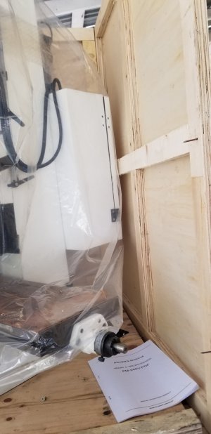
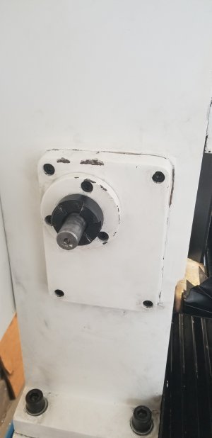
There are other problems which are just poor workmanship. One of them: When the mill arrived the nuts, washers, bearings, holding the bottom of the lead screw had fallen off and fortunately were still on the pallet. I had no idea where they went, but figure it out after using the machine a while. I initially thought maybe this was why the head was falling, but now I think it was just another contributor. See the beginning of this posting string to see the parts. I am not the only one who found them to be a problem.
https://www.hobby-machinist.com/threads/pm-940m-cnc-z-axis-bearings.59538/#post-608202
Good luck.
Dave
PS. I am thinking about putting some pulleys on the top of the column, hooking cables to the head, routing them through the pulleys and using the cables to the dangling some counter weights down the back of the column . I would only need about 300#s of weights! Maybe some air springs instead of more weight on the poor column and swing around.