PM1440GT Is in the shop!

I agree with others. Add the 2 Channel switch to get the two times. To avoid wear on the belts etc I run the longer braking time except when I really need the shorter braking time, i.e. using the proximity stop or doing it manually. It is just a switch and another wire back to the VFD input. However, I can see why you might not want to mess with your front panel clean look. Maybe a mini-switch. They are also quite reliable.

Dave L.
 
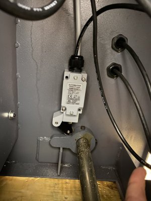
Got the new footswitch installed. It's a huge switch so it needed to be moved from the factory location.

Wires run for the footswitch as well as the forward and reverse contactor.

By the end of the weekend I hope to have the motor spinning.
 

Attachments

  • 22-02-02 18-12-20 6940.jpg
    22-02-02 18-12-20 6940.jpg
    80.2 KB · Views: 72
Gang, could use some help locating the 8 conductor VFD control cable... Just need a part number or supplier that sells less than 1000ft. Having a hard time.
 
I think you only need the shielding on the 3-conductor speed control and power to the motor. At least I hope that is the case because that is what I am using.
 
Dummy electrical question.

To recap, I have all of my stock controls working and the high voltage wiring removed from the FWD and REV contactor.
1643937054312.png


So there's the factory 24v system going through all of the controls.

And I'm going through the docs I've referenced previously, and see something like this:
1643939760391.png


If I am keeping the factory 24v system and interlocks, does the VFD 24v (P24) need to go through the e-stop, in this example?

I was planning on running VFD P24 through the contactors as noted in the first picture. I don't see a safety/interlock concern, because the footbrake, e-stop, and FW/REV circuits would all still work on the factory 24v system and break any input to the VFD by way of releasing the contactors.

Admittely, I am a dummy so let me hear it.
 
I would/did wire P24 thru an additional contact on the E-stop. Some drives require a 1 on the stop input before the drive will run. Removing that 1 indicates you want to stop now. Having dual contacts on the switches allows the factory control to operate as original and the extra contact is wired for the drive logic inputs.

For wire, I think I ordered most of mine from Wire & Cable Your Way.
 
Running the P24 through a separate switch block is an additional level of redundancy/safety. If for some reason a contactor did not release or a spindle control failed closed, it adds 2 serial actions that discontinue the VFD signaling process. Very unlikely to have a contactor fail closed, and the current E-Stop kills power to the contactors so they would go open. So it is an option as an additional safety, to how the current controls work. P24/VFD input power is completely separate from the 24VAC that controls the lathe relay/contactors.
 
Back
Top