POTD- PROJECT OF THE DAY: What Did You Make In Your Shop Today?

View attachment 457026
Started organizing the shop by sorting and labeling stuff. Takes a lot more time and Coca-Cola than I initially thought.

It’s a shame that Big Gulp doesn’t exist in Finland.
organizing is a losing battle.. you are never done.. ask me I know.
looks like you are heads above everyone.
stay away from the burger king, he'll own you.

looks like you haven't done much... And you are already taking a break????

Oh, I thought this was the joke thread... sorry for using this for my entertainment.
 
Yep, I can see why she was creeped out... the blonde hair and brown eyebrows. She must have been scared :rolleyes: .
How does that work as a trauma neck stand in with no neck or torso? where does the support go?
 
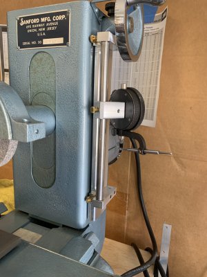
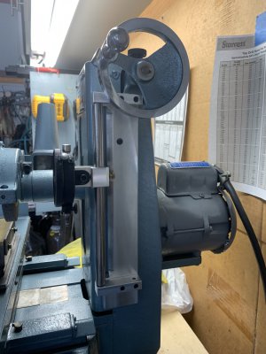
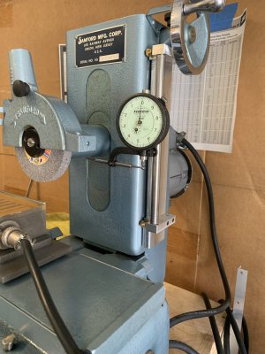
Today's project was to rig a .0001 indicator on the grinder. I had to ponder this one for a day or two for a couple of reasons. First off, I wanted to be able to raise the wheel and come back down to the indicator (think dressing the stone), 2) going direct to the indicator has everything in take away. I have enough trouble with addition, you add take away to the equation and I'm toast. Besides, subtraction has sooo many negative annotations. The best I could do was to use my teeter totter (Starrett indicator hole attachment). By using the teeter totter I can reference off the bottom of the spindle housing. By default, I can raise the wheel without loosing my place. Yes, I have to watch my depth, but .100 is a long way in this sport. I think I would need to watch my depth if my indicator was above my spindle as well, going to far would simply unload the indicator and then I would get no reading.
The mission, as always, was to find a way to put this on without modifying the grinder. Fortunately, there was a couple of #8 cover screws that were in a great place. They are tapped into the vertical casting so they should be pretty solid for this project. By using these two holes, I was able to not make any modifications to the grinder. Also, as usual, had to make it out of scrap on hand, no fair buying new beautiful aluminum or TGP rod. Thank you fly cutter for helping me rub the boogers off old metal. The rod was a piece of rusty drill rod, but it cleaned up good nuff for this job.
IMG_0261.jpgIMG_0263.jpg
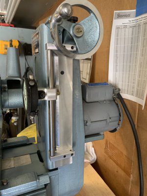
I set it up so that I can pivot the rod or pivot the clamp to move the indicator out of the way if I choose. If I pivot the rod, I stay in the wheel house on my set up. The rod has a shoulder turned on the ends, so it cant go far.
IMG_0262.jpgIMG_0265.jpg
Here is what I have observed so far:
  • The Z wheel is marked with .0005 graduations. The main reason I took this abuse was because I found the best finishes and least amount of heat in adjustments between those graduations or .0002 to .0003.
  • For now, I cant hit the .0001. The machine seems to settle just a bit with each adjustment if the motor is running. Not bad, but near .0001 according to the indicator. This was an eye opener for me but it should not have been. As the wheel lowers, the nut is on the unloaded side of the threads. .0002 is more than fine, I didn't put the indicator on in hopes of being able to make .0001 adjustments, just a little more granularity than I was getting.
  • My biggest fear was vibration showing up in the indicator. For the most part, it is non existent. I do see a real tiny movement in the hand when the unit is running, but it is small.
  • The indicator tracks close to the hand wheel. Seems to pick up a tenth or two per hand wheel revolution. Doesn't seem like a big deal since it would be a lot of grinding to use up one complete rev.
For now, I am indicating off the bottom of the spindle housing. I may bore another piece of half inch aluminum to clamp onto the spindle housing and put a flat on the bottom to indicate from. After the paint cures.
 
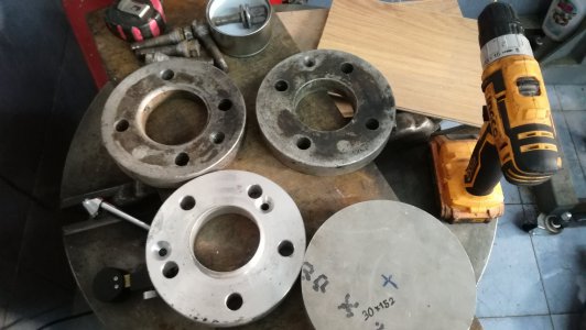
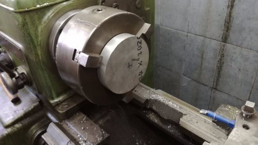
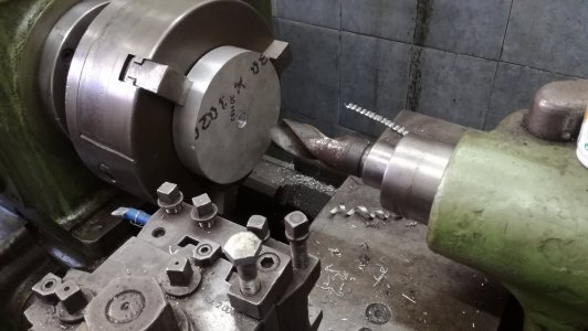
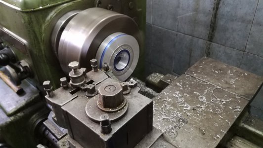
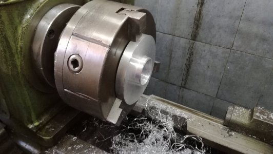
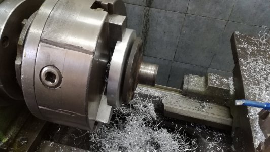
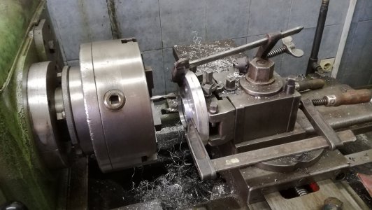
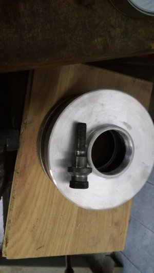
Today i machine one wheel spacer and modify the other, i started with 152x30 mm piece of aluminium, drill then cut down to size for the rim regester. Then i fip it and counterbore the back side to apsect the wheel hub, i have a spare hub for checking. Then came time to drill the holes and elongated couple on the 5 hole spacer, i also took 2mm off the back to make it 18mm thick, i'll fill the unused holes with epoxy just to make me feel good. I did make one wheel bolt like the back bolts, using a bolt just making a flat style head for them, now to make 7 more.
IMG_20230803_170838.jpgIMG_20230804_114142.jpgIMG_20230804_114843.jpgIMG_20230804_120905.jpgIMG_20230804_124829_1.jpgIMG_20230804_130124.jpgIMG_20230806_124530.jpgIMG_20230806_223241.jpg
 
Today's project was to rig a .0001 indicator on the grinder. I had to ponder this one for a day or two for a couple of reasons. First off, I wanted to be able to raise the wheel and come back down to the indicator (think dressing the stone), 2) going direct to the indicator has everything in take away. I have enough trouble with addition, you add take away to the equation and I'm toast. Besides, subtraction has sooo many negative annotations. The best I could do was to use my teeter totter (Starrett indicator hole attachment). By using the teeter totter I can reference off the bottom of the spindle housing. By default, I can raise the wheel without loosing my place. Yes, I have to watch my depth, but .100 is a long way in this sport. I think I would need to watch my depth if my indicator was above my spindle as well, going to far would simply unload the indicator and then I would get no reading.
The mission, as always, was to find a way to put this on without modifying the grinder. Fortunately, there was a couple of #8 cover screws that were in a great place. They are tapped into the vertical casting so they should be pretty solid for this project. By using these two holes, I was able to not make any modifications to the grinder. Also, as usual, had to make it out of scrap on hand, no fair buying new beautiful aluminum or TGP rod. Thank you fly cutter for helping me rub the boogers off old metal. The rod was a piece of rusty drill rod, but it cleaned up good nuff for this job.
View attachment 457035View attachment 457036
I set it up so that I can pivot the rod or pivot the clamp to move the indicator out of the way if I choose. If I pivot the rod, I stay in the wheel house on my set up. The rod has a shoulder turned on the ends, so it cant go far.
View attachment 457037View attachment 457039
Here is what I have observed so far:
  • The Z wheel is marked with .0005 graduations. The main reason I took this abuse was because I found the best finishes and least amount of heat in adjustments between those graduations or .0002 to .0003.
  • For now, I cant hit the .0001. The machine seems to settle just a bit with each adjustment if the motor is running. Not bad, but near .0001 according to the indicator. This was an eye opener for me but it should not have been. As the wheel lowers, the nut is on the unloaded side of the threads. .0002 is more than fine, I didn't put the indicator on in hopes of being able to make .0001 adjustments, just a little more granularity than I was getting.
  • My biggest fear was vibration showing up in the indicator. For the most part, it is non existent. I do see a real tiny movement in the hand when the unit is running, but it is small.
  • The indicator tracks close to the hand wheel. Seems to pick up a tenth or two per hand wheel revolution. Doesn't seem like a big deal since it would be a lot of grinding to use up one complete rev.
For now, I am indicating off the bottom of the spindle housing. I may bore another piece of half inch aluminum to clamp onto the spindle housing and put a flat on the bottom to indicate from. After the paint cures.
Let me know when you are done with the upgrades and I can stop by to pick it up.:D

You are killing me with the updates and how amazing everything is looking. Looking forward to a video as well.
 
Let me know when you are done with the upgrades and I can stop by to pick it up.:D

You are killing me with the updates and how amazing everything is looking. Looking forward to a video as well.
Thank you. It is a neat little machine. My Kurt vise is old. I am thinking that when I get a minute, I might try grinding the jaws. I can see a dip in the jaws when I am tramming the vise. Maybe I can video a portion of that project. In the meantime, keep the pics of the build project coming. I think it is going to be great
 
How does that work as a trauma neck stand in with no neck or torso?
Very poorly :chunky:

Hans originally came with a torso and a carrying case for him to travel in from an expo to another. Those were already missing when I got him.

He has a neck though, but it doesn’t show in the pictures.
 
Last edited:
Back
Top