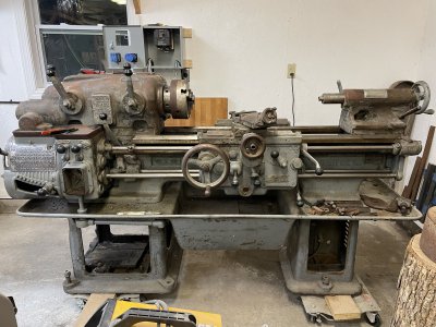
Pratt & Whitney Model C 12x30 lathe

@hustlebird & @motormech1 : I absolutely think the missing taper attachment pieces could be fabricated. You’re right that the later model c’s had several revisions, but I think most of these were with the tail end of the saddle and cross slide. The biggest change was the addition of ball bearings on the slide housing on the backend of the saddle. I believe they may have made this change to make for a smoother travel when using the relieving attachment.

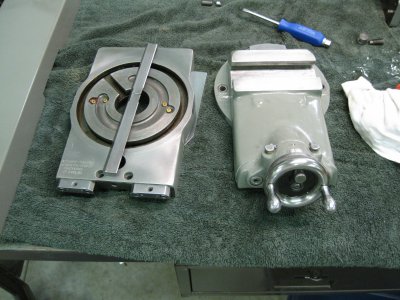
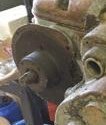
If you look at my shoe, one set of bearings at each end are stationary and the other set of bearing are staggered and on an eccentric cam. This allows it to be adjusted for clearance. In the middle of mine you can see the ACME screw that the saddle portion of the taper attachment picks up. Mine was missing the special tool for this. I’m not sure what the original looked like so this is what I came up with.

I don’t know how much all this helps with the earlier taper attachments, but I believe though some of the specifics are different the concepts are the same.

I took some pictures of mine – the shoe, the taper and the special tool. If I could help with measurements or additional pictures, just let me know.

View attachment 436465 View attachment 436466 View attachment 436467 View attachment 436468
Geezzzzzz that's gorgeous! Honestly puts it a step above my 10EE IMHO!!!!
 
I wasn’t really recommending that you flush the headstock but just sharing a way that I have done them before. Mine was pretty clean also. I’ve posted a picture of my headstock. I’m curious if there are any changes in mine from your earlier model. I’ve also included a picture of the headstock oil filter housing. Mine had a relief valve and the filter you see. The lower piece of this housing has a cavity that allows sediment to settle in.

View attachment 436817 View attachment 436816

As far as the apron goes, I would recommend pulling the saddle and pulling out the volume rods and changing the bijur metering units as these tend to plug. The volume rods also collect quite a bit of sediment which if not flushed out will find its way to the metering units. I’ve included a picture of the volume rods and the metering units below. These are a bit of a puzzle as they have to come out in the order I have them laid out.

View attachment 436815

I would also recommend as a minimum to pull the bijur pump on the apron as this has a filter in the pick-up. To pull this pump you’ll have to get to the back of the apron. The pump is connected to an access cover there. This pump is also connected to a distribution manifold that can be accessed from the front side of the apron. The pump must be disconnected from the manifold before you can pull the pump. There is an interlock for the half nuts on the inside of the apron front cover that will need to be triggered for the cover to be released or when reinstalling. I believe you can trigger this interlock with the saddle off. If you don’t pull the saddle, it will take a little more explanation.

View attachment 436811 View attachment 436812 View attachment 436814

There is also one of these bijur pumps in the feed gearbox. Below is a picture of it. Both pumps operate off of a fork that provides the pumping action.

View attachment 436813

I hope the pictures make this all easier to understand.
Monarch experience & research with the Bjours. In a production setting change once a year. YMMV but they do clog up, need to watch they are passing oil. They are sized for the length of the oil line, so pay close attention when removing them. On Monarchs the lines are known to corrode, they were put in place with melted sulfur. On a Square Dial Monarch running the feed rod will run the apron pump to get the oil flowing. Because of the small size of the port, priming the Bjours can be a PIA. Went better after I learned about running the feed rod.
 
I came across some of the same issues that you were talking about when I worked on my ’68 machine and my friends ‘54. The 10EE uses a pressurized constant low volume of oil. It works well if in good condition and supplied with clean oil. I believe this system was designed to be more automated and less operator dependent. Its weakness is short, intermittent use. But even this can be overcome with a simple start-up procedure, as you said.

The Pratt & Whitney uses a pumping system which has a much higher volume. It’s pumping action is connected to the clutch use. The meter valves are freer flowing than in the 10EE. Although I can’t remember each valve’s size, they’re marked when you pull them out.

The volume rods in the Pratt & Whitney allow for a supply of oil to be housed in the saddle. This allows for good oiling without too much waste. This pump also oils the key elements in the apron.

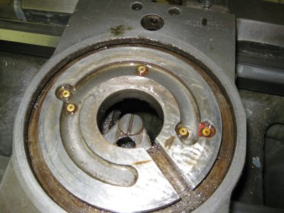
The cross-slide and compound are oiled by two oil cups located at the compound handle. One lubricates the compound ways and screw. The other oils the cross-slide by filling a circular reservoir located below the compound and is metered by some small reduction nozzles. This is all gravity fed.

Pratt & Whitney has a good combination of quick oil delivery where it’s needed with a minimum of waste.

Below is a couple of pictures of the oil galleries underneath the compound and the oil cups next to the compound handle.

IMG_1332.JPG IMG_2069.JPG
 
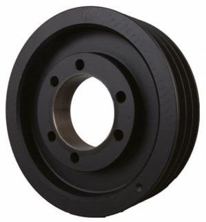
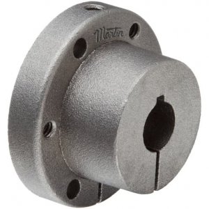
Quick update, got a new input pulley ordered thanks to the measurement you provided, @tailstock4. Thanks again! I had to settled for a modular bolt in bushing type as the only one I could find as a one piece finish bored/keyed was around $3k! I couldn't believe it actually. Anyway, it ended up about $400 for the pulley and bushing. I'm almost positive the back side will need some amount of clearancing for the casting bump out where I presume a bearing lives. Now, if the motor shop would just get the motor back to me...
71653564-2DCD-43EB-8C5E-C01835D37230.jpeg
42EED5CE-B7E3-4C4E-94DC-2A8FBB87721D.jpeg
771ED49C-D099-4BC5-B5F0-907A2BA5B850.jpeg
 
I watch ebay for NOS taper bushing sheaves. TB Woods are my favorite because i have the size table but Martin, Matco, Browning are all good. $100 for both is the most I've paid, $75 is more normal. Lots of ebay stuff is overpriced but pulleys and bushings are a good deal. Dave
 
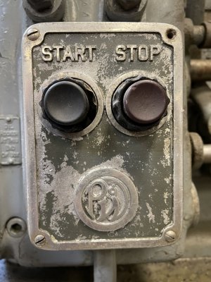
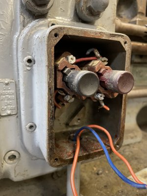
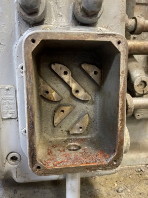
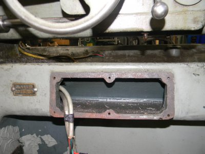
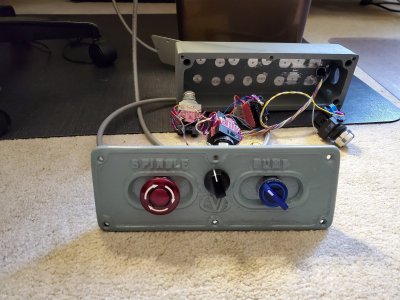
Got the VFD mounted up and a little wiring started and decided to prep the lathe to run the new wiring. I pulled the old motor wiring and cut the magnetic contactor out of the loop, pulled the main switch panel and removed the old switches. I'm going to fit the new VFD control switches in the factory switch plate to keep it looking original.

54129FF9-F80C-434F-892E-7F48DCEC2804.jpegA9D5EFAC-E5F4-417D-9D79-86D5DEDE8A7A.jpeg
1F6BAE9F-61E5-4FB2-9704-4C801C5426A3.jpeg26127B41-E48E-4D09-9EC5-10F1467195EF.jpeg
 
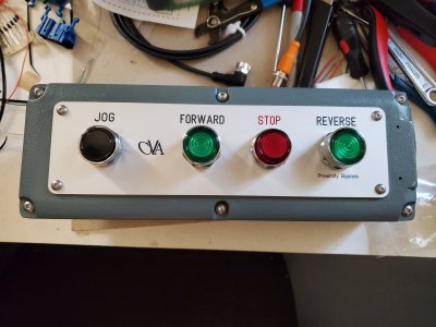
Similar Idea, I had been asked to build a VFD system for a CVA lathe and opted to keep the original casting for one of the controls similar to your style, I added a speed pot and replaced the switch gear which required modifying the cast iron face. I added a separate cast metal control box for the direction and Jog switches and had a face plate made.
DSCN4191.JPG
CVA Lathe 2.jpg
CVA Upper Control Enclosure.jpg
 
Got the VFD mounted up and a little wiring started and decided to prep the lathe to run the new wiring. I pulled the old motor wiring and cut the magnetic contactor out of the loop, pulled the main switch panel and removed the old switches. I'm going to fit the new VFD control switches in the factory switch plate to keep it looking original.

View attachment 438243View attachment 438245
View attachment 438248View attachment 438249
Looking good! My box is in the same place, but I had a cheap 2 switch cover on it, nothing cool like that original one! I replaced the faceplate with one I could fit 4 switches in, ran an estop and a start button for my VFD.

Are you going to run past 60hz with it? I haven't yet, but thought the 1500rpm variants was just adjusted pully ratios right? I never really dug into that, but had always meant to. Maybe @tailstock4 has some insight into those? that extra 500 rpm would be handy...
 
@mksj That's a nice setup! I'm putting a 3 way switch in one spot and a potentiometer in the other. If I decide I need a jog I'll have to figure something out.
 
Last edited:
@hustlebird This is what tailstock said about speeds:
One thing to be aware of is the input shaft speed should be no lower than 500 rpm or higher than 1,000 rpm because of the oiling system.

Really, 1,000 rpm works pretty well if I stay with positive tooling or high speed steel.
 
Back
Top