- Joined
- Feb 2, 2014
- Messages
- 1,061
Since the lock down I have been staying close to the shop and needed something to make I built a David Kerzel hit miss engine from plans. This is where the Chinese got the design of one of their engines they sell. I stayed close to the plans on this engine with just a few changes.
That model went along very nicely and is very reliable and starts on the second spin. I have been able to slow it down considerably as most model engines run far too fast as compared to the full size engines of the same design.
During this time I had ordered a casting kit for a Bob Shores Eagle engine. That casting kit got delayed in Detroit for two weeks so the Kerzel engine got first in line. The Bob shores engine has since also been completed and it runs fine but still not slow enough to suit me. I used the plans as a suggestion and the castings as raw material to build an engine that does resemble the original but that is about all, I changed about everything.
So now I want to build an engine my way with no plans, no drawings, and my little experience. Come along and see how things progress as I started this project about a week ago and will bring you up to speed quickly.
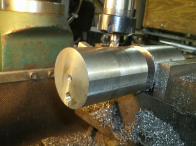
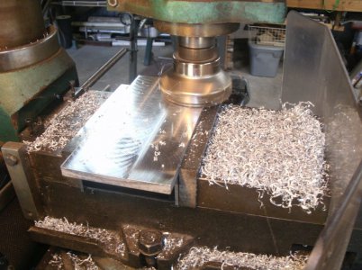
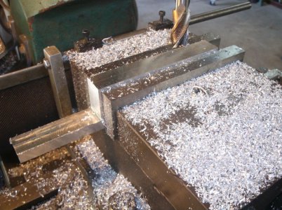
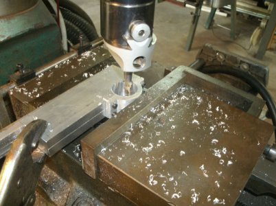
I started with this big chunk of aluminum 3.5" X 3.5" with the idea of having a larger cooling water tank and a larger piston. I cut 5/8" off the top to make the top water cover.
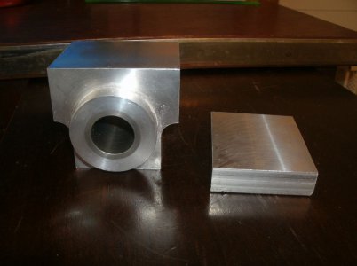
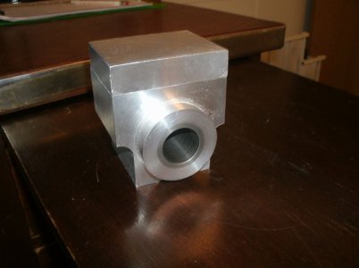
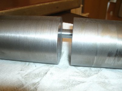
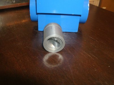
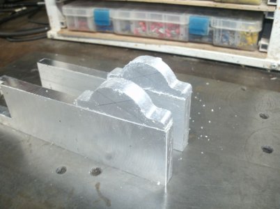
As you can see I have done some sculpting on the sides and installed a cast iron piston liner.
I decided on a 1" diameter piston because that is all the bigger I can go with the size of the cast iron rod I have on the shelf to make the liner. Many of the dimensions and sizes of the parts will be determined by what materials I have on hand.
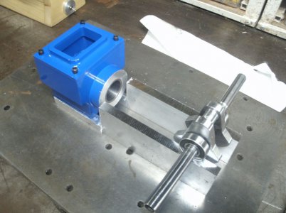
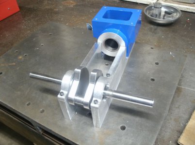
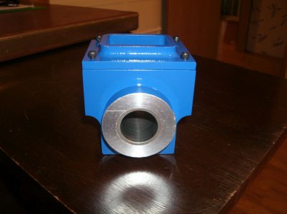
Here it is with the fancy top and painted Royal Blue, thats where I got the engine name. Why did I paint it now and not wait until after all the holes are drilled and everything fitted? I just can"t bring my self to disassemble something that is working perfectly fine just to paint it. This will also make me be more careful so not to scratch the paint.
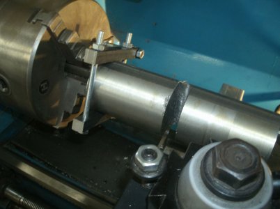
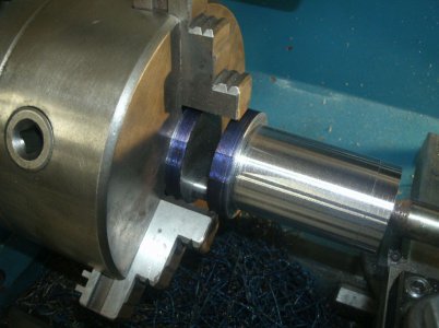
A chunk of 2.300 diameter solid steel about 8" long.
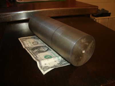
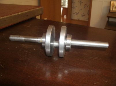
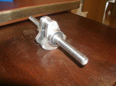
I did not weigh it but it is a good chunk and inside there somewhere is a crank shaft. (I hope)
That's all for today.
Thanks for looking
Ray
That model went along very nicely and is very reliable and starts on the second spin. I have been able to slow it down considerably as most model engines run far too fast as compared to the full size engines of the same design.
During this time I had ordered a casting kit for a Bob Shores Eagle engine. That casting kit got delayed in Detroit for two weeks so the Kerzel engine got first in line. The Bob shores engine has since also been completed and it runs fine but still not slow enough to suit me. I used the plans as a suggestion and the castings as raw material to build an engine that does resemble the original but that is about all, I changed about everything.
So now I want to build an engine my way with no plans, no drawings, and my little experience. Come along and see how things progress as I started this project about a week ago and will bring you up to speed quickly.
I started with this big chunk of aluminum 3.5" X 3.5" with the idea of having a larger cooling water tank and a larger piston. I cut 5/8" off the top to make the top water cover.


As you can see I have done some sculpting on the sides and installed a cast iron piston liner.
I decided on a 1" diameter piston because that is all the bigger I can go with the size of the cast iron rod I have on the shelf to make the liner. Many of the dimensions and sizes of the parts will be determined by what materials I have on hand.
Here it is with the fancy top and painted Royal Blue, thats where I got the engine name. Why did I paint it now and not wait until after all the holes are drilled and everything fitted? I just can"t bring my self to disassemble something that is working perfectly fine just to paint it. This will also make me be more careful so not to scratch the paint.

A chunk of 2.300 diameter solid steel about 8" long.

I did not weigh it but it is a good chunk and inside there somewhere is a crank shaft. (I hope)
That's all for today.
Thanks for looking
Ray
Last edited:


