-
Welcome back Guest! Did you know you can mentor other members here at H-M? If not, please check out our Relaunch of Hobby Machinist Mentoring Program!
You are using an out of date browser. It may not display this or other websites correctly.
You should upgrade or use an alternative browser.
You should upgrade or use an alternative browser.
seized spindle bearings
- Thread starter savarin
- Start date
- Joined
- Aug 22, 2012
- Messages
- 4,115
It was not as difficult as I thought it would be.
I snipped the cage and removed it then supported it on end in the vise with aluminium jaws, tapped with a drift around the shield which moved the cone sufficiently to engage the old two screwdrivers trick.
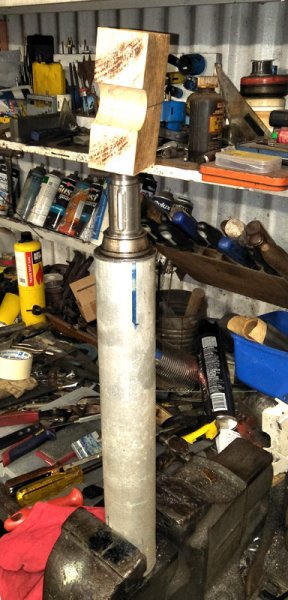
This slid it off the first landing and to get it off the second landing I found a length of ag pipe that just let the spindle nose pass through but not the metal shield, stuck some rags in the bottom of the pipe so the end wouldnt get damaged when it fell through and whaled on the end with a chunk of wood and a hammer.
Now comes the most difficult part, removing sufficient material from the left hand bearing seat so the bearing will slide with a tight but hand pressure fit so the end float can be adjusted. I think this was the problem with the original set up, they were installed together way too tight and that eventually wore them out.
I snipped the cage and removed it then supported it on end in the vise with aluminium jaws, tapped with a drift around the shield which moved the cone sufficiently to engage the old two screwdrivers trick.
This slid it off the first landing and to get it off the second landing I found a length of ag pipe that just let the spindle nose pass through but not the metal shield, stuck some rags in the bottom of the pipe so the end wouldnt get damaged when it fell through and whaled on the end with a chunk of wood and a hammer.

Now comes the most difficult part, removing sufficient material from the left hand bearing seat so the bearing will slide with a tight but hand pressure fit so the end float can be adjusted. I think this was the problem with the original set up, they were installed together way too tight and that eventually wore them out.
- Joined
- Sep 5, 2014
- Messages
- 428
Since you don't have lathe to spin it, just pretend you are a shoe shine boy with emery cloth strip. Just work your way around it. Filing takes more skill to stay round.
- Joined
- Aug 22, 2012
- Messages
- 4,115
Got the bearings today, SKF,
Not a chance of it sliding on so I used these tools to reduce the diameter.
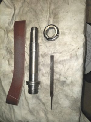
Shoe shining with the belt then an ultra fine file to remove those scratches.
Only took a couple of attempts till the bearing slid on with tight hand pressure.
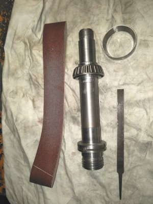
So quick and simple I think I will do the chuck end tomorow as well.
Not a chance of it sliding on so I used these tools to reduce the diameter.

Shoe shining with the belt then an ultra fine file to remove those scratches.
Only took a couple of attempts till the bearing slid on with tight hand pressure.

So quick and simple I think I will do the chuck end tomorow as well.
Got the bearings today, SKF,
Not a chance of it sliding on so I used these tools to reduce the diameter.
View attachment 281979
Shoe shining with the belt then an ultra fine file to remove those scratches.
Only took a couple of attempts till the bearing slid on with tight hand pressure.
View attachment 281980
So quick and simple I think I will do the chuck end tomorow as well.
The chuck end bearing carries most of the radial load. You do not want that bearing to be loose, you want it to be a interference/press fit. If it's loose it will tend to fret (become more loose) over time which will affect surface finish. The repair is a replacement spindle. Food for thought.
- Joined
- Apr 28, 2014
- Messages
- 3,590
What about using some Loc-Tite (or DU eq.) bearing retaining compound?
- Joined
- Sep 5, 2014
- Messages
- 428
At the float end was were he was having difficulties,. There is no need to glue up anything. I slid the chuck end cone on by leaving the spindle in the freezer for a while and putting the cone under a heat lamp. Remember The Seal. You do want a bit of an interference fit. At work , I used a induction heater and wouldn't bother with the freezing the shaft . Though I've never did this way, it might be the best way, heat the bearing in pan of oil. Rubber gloves would be needed.
Once together , I checked the turning by hand and the bearing clearance , I'll say this in Australian, a 2 meter long 4x2 timber to pry up and a fine dial indicator. Back to imperial, I used a 1/10th dial indicator. I got 1/10th, which is what it was before .When turning by hand ,you don't want to feel the individual rollers. After running for a while, come back and check, you may have to check your clearance as things seat.
Good luck. Ray
Last edited:
- Joined
- Aug 22, 2012
- Messages
- 4,115
I followed the idea from the pdf above of reducing the diameter of the old bearing outer ring to use as a pusher.
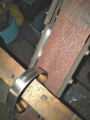
I found by angling the wooden batton I could get the ring to spin fast but sand off material as well.
It took only 5 mins to get to where it was a free fit into the headstock.
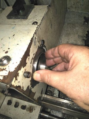
I'm glad it didn't take long because as I got everything together I suddenly found a chunk of aluminium casting that had been turned down for a spacer ages ago (never throw anything away) that fit perfectly and made the job easy.
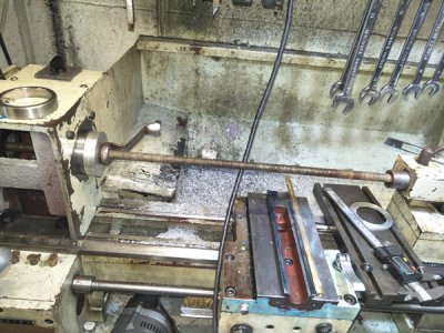
by slipping the end of the all thread into the tail stock it kept it straight and the new parts went in easily but a tight fit.
I also fitted the grease shields back in place.
The mega down side later was I distorted the roller cage getting that part onto the spindle and all the rollers fell out.
Luckily they fell onto the cloth and I never lost any.
I learnt two things here -
1. use a proper fitting tube drift to install the cone so as not to damage the cage.
2. the rollers are tapered so only fit in one way. Now thinking about it of course they have to be tapered and it says "taper roller bearing" but it had never crossed my mind before.
It took a bit of fiddling to get the pre load correct but it runs very smoothly now and 20 mins flat out only got to pleasantly hot, ie can be held in the hand. 40 mins at low speed barely raised the temp.
It is way smoother than when new but I havnt used it to do anything yet.
I decided to drill for grease nipples so the bearings wouldnt dry out and maybe last more than 6 years this time.
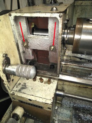
I know its under the speed plate but it wont be a weekly job.
I couldnt place them on the top as the inside of the casting doesnt reach the bearing housing.
So I wont have an excuse not to do it I will replace the screws with knurled ones.

I found by angling the wooden batton I could get the ring to spin fast but sand off material as well.
It took only 5 mins to get to where it was a free fit into the headstock.

I'm glad it didn't take long because as I got everything together I suddenly found a chunk of aluminium casting that had been turned down for a spacer ages ago (never throw anything away) that fit perfectly and made the job easy.

by slipping the end of the all thread into the tail stock it kept it straight and the new parts went in easily but a tight fit.
I also fitted the grease shields back in place.
The mega down side later was I distorted the roller cage getting that part onto the spindle and all the rollers fell out.
Luckily they fell onto the cloth and I never lost any.
I learnt two things here -
1. use a proper fitting tube drift to install the cone so as not to damage the cage.
2. the rollers are tapered so only fit in one way. Now thinking about it of course they have to be tapered and it says "taper roller bearing" but it had never crossed my mind before.
It took a bit of fiddling to get the pre load correct but it runs very smoothly now and 20 mins flat out only got to pleasantly hot, ie can be held in the hand. 40 mins at low speed barely raised the temp.
It is way smoother than when new but I havnt used it to do anything yet.
I decided to drill for grease nipples so the bearings wouldnt dry out and maybe last more than 6 years this time.

I know its under the speed plate but it wont be a weekly job.
I couldnt place them on the top as the inside of the casting doesnt reach the bearing housing.
So I wont have an excuse not to do it I will replace the screws with knurled ones.

