Here I go making a bunch of long posts in Tony's thread. This is a description of the steps I used to create the baffles for the Howard DGA-8 wheels pants shown in the previous postings in the thread. This was originally posted on the Biplane Forum.
========================
Both wheel pants are welded and fairly well finished in terms of the aluminum shaping and planishing. The subject of this post will be the 'baffles' which are installed behind the tire to prevent mud/snow/water/ice from collecting in the aft part of the pants. There is no front baffle on the Howard pants since the tire is close to the front of the pant anyway.
The drawings for the pant show a location for the baffle which is very close to the tire opening and the tire itself. I'm going to let it sit a little farther aft to insure clearance and allow me the option of putting a doubler around the tire opening to stiffen it. Photos of a mangled original seem to show they doubled the opening edges and these are pretty thin on our pants even though we're using .063" material instead of .050". Locating the baffle on the pant itself was a bit of a PITA but it's doesn't have to be perfect considering its function. Once I got some reference lines inside and outside the pant I made a template of the outside to use as a guide to produce the forming block. The outside template is nice but you have to offset the profile enough to allow for two thicknesses of metal plus some springback. And you have to expect the first part to be 'close but no cigar' which will tell you what changes need to be made to the form block to get the baffle the correct shape and size.
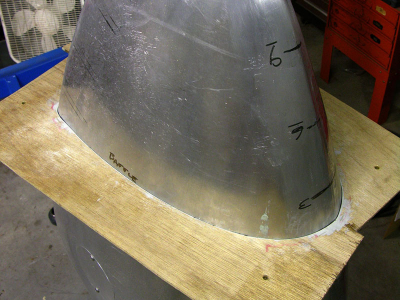
The template was done in two halves, then glued together. I didn't like the accuracy so I added some Bondo to the edges to fill the gaps -- apply Bondo the the edge, stick some waxed paper over the Bondo, then slide it onto the pant.
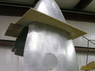
After the Bondo cured I sanded the excess off so the template would lay flat.
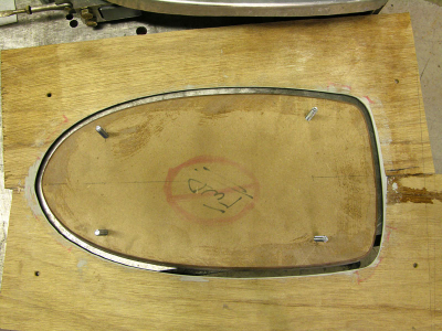
Big gap to the template. Didn't start out that way but it was clear the form block was too large so I took a bunch more off. Maybe too much.... but good enough for a test part.
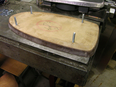
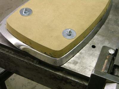
The block is 3/4" MDF. The dark color on the beveled edges of the block is polyester resin. I soaked the working edges with it and then did a final cleanup sanding. The resin makes the block tougher so it doesn't just crumble when you beat on it.
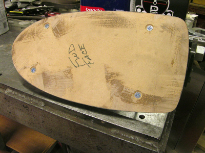
I used four 1/4-20 screws to join the two blocks. They keep some pressure on the panel and keep things lined up.
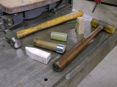
My high-tech tool assortment. The ball peen hammer is for use on the corking tools. The plastic hammer can be used directly on the metal. The little block with the modified pencil is my 1/8" offset marking tool. Probably needs to be more like 1/4".
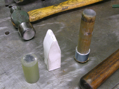
The corking tools are;
A short piece of 1" FG rod, flat on one side and slightly rounded on the other. Both ends get used and the rod is tough enough that beating on it with a hammer does no harm.
The white (unknown type of) plastic wedge is great for forming tucks and shrinking but it needs to be re-shaped often due to wear.
The wood dowel has a slightly rounded face which also needs to be refreshed often. The hammer end has an aluminum tube pressed over it so the hammer blows don't destroy the wood too quickly.
I had serious concerns about being able to form the baffle without slitting and welding the tight radius corners. So I didn't document the first part of my adventures. But I did get away with it and I have one tight corner left so I'll show you folks how I did it.
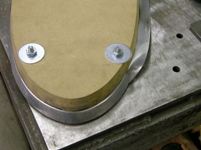
This section is where I started. I had previously annealed the edge of the aluminum (3003) so it was nice and soft. It fought with me a little bit but I got the flange formed across the top of the part.
This one went too but I was glad I started with the easier one! The flat-ish sections in between the tight corners formed pretty easily.
Stay tuned, more to come..........
