

-
Welcome back Guest! Did you know you can mentor other members here at H-M? If not, please check out our Relaunch of Hobby Machinist Mentoring Program!
You are using an out of date browser. It may not display this or other websites correctly.
You should upgrade or use an alternative browser.
You should upgrade or use an alternative browser.
Shop built CNC Mill Project
- Thread starter RebelJD
- Start date
Centroid software doesn't know, or care, what type of switch is used. I'm using the "All Home" function. All 3 switches are NC and wired in series to single input. When a Home sequence is initiated (M91 or M92 with an M26) the axis will move at the slow jog rate until it detects the limit switch is opened. It then reverses until the limit switch is closed again and moves another .005". I set it up to home the Z axis first so any tooling will clear before the X and then the Y move. I'm using high quality limit switches to get the best repeatability. There is always the debate as to whether a mechanical switch or a proximity switch has better repeatability, but I've had good success with the mechanical switches. I've tested the homing sequence many times and it repeats to the same exact position each time on all 3 axis.
In a non-hobby application, the control will look for an index pulse from an encoder or linear scale to set the home position to, but with the open loop steppers I'm using this is the best I can do.
In a non-hobby application, the control will look for an index pulse from an encoder or linear scale to set the home position to, but with the open loop steppers I'm using this is the best I can do.
I now have the wiring complete, and machine is functional again. When I first started the control system, I bench tested everything by mounting it to a piece of plywood. I began with the Centroid Acorn main board, the relay output board and the small DC power supply. I then connected it to the Lenova PC which runs Windows 10 and the Centroid software. I'm using an Acer touch screen monitor and a wireless keyboard. Once I got all of that working and configured, I added the stepper drives and initially the treadmill DC motor controller. I installed the three axis motors and spindle motor on the machine and wired them temporarily. I also wired up the 3 home limit switches.
The small circuit board in the upper right of the plywood is an Arduino based interface board I built to convert the 10v analog spindle speed reference signal from the Acorn board to a PWM signal required by the treadmill controller shown to its right. The motor is also shown. While this did work, the speed regulation was just not sufficient for a CNC mill spindle.


So, I decided to use an AC Servo Drive as the spindle drive, but this presented a challenge. The Servo and Motor I bought was a Chinese Import with a part number 110ST-M05030 rated at 1.5KW. These are fairly common, but the documentation is poorly translated, so it took some internet research and some experimentation to figure everything out.
I thought it might be useful to some others so I'm going to provide a lot of detail on what it took to make this work. The speed regulation and response are terrific. I'm really glad I went this route.
The Acorn board outputs a 0 to +10 Volt DC spindle speed reference signal but the AC Servo drive needs a -10 to +10 volt dc signal for CW and CCW rotation. The Acorn board can also be configured to output a PWM spindle speed reference signal but that is not compatible with the AC Servo drive either. However, the AC Servo drive can be configured to accept Step & Direction signals just like a stepper drive. So what to do?
I found an interface board (C89) sold by CNC4PC that will accept the 0 to + 10 volt signal (or the PWM) along with the VFD Direction signal from the Acorn and produce a -10 to +10 analog signal that would be compatible with the AC Servo. So, I purchased this board but could not get it to work. CNC4PC could never tell me if the board was bad or if it was a bad design. I worked with them for over 3 weeks trouble shooting the problem and got nowhere. I'm a retired Electrical Engineer with considerable experience in industrial control systems so I knew the board was not working as advertised. I typically don't do reviews on companies, but their customer service was awful, and I'll never do business with them again.
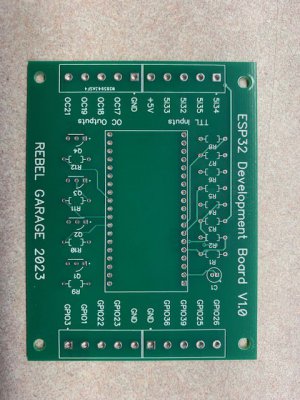
I bought the C89 board so I wouldn't have to develop my own interface board again, but that is what I finally did. This time I used a ESP32 microcontroller and had my own circuit board built. It takes the PWM signal from the Acorn board and converts it to a Step pulse signal for the AC Servo Drive. I also used the VFD Direction signal from the Acorn and connected it to the AC Servo Drive to control direction. This an entirely digital solution and it works great.
Here is the schematic for the interface and parameter settings for the AC Servo. The minimum order on the circuit board was 10 so I have few left over. I'm not interested in selling complete boards, but I would be willing to sell the extra boards cheap and share all the details needed to build your own if you are interested. Send me a PM if you want.


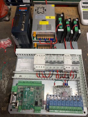
Once I got all this working on the bench, I assembled the back panel for the electrical enclosure and tested everything again. It's much easier to debug things with the panel on bench rather than mounted in the enclosure.
Across the top left to right is the AC Servo for the spindle, two 48dc power supplies for the stepper drives and then stepper drives. In the middle is the spindle speed conversion board and circuit breakers and contactors. The bottom row has the Acorn board on the left and the relay output board sitting above the DC power supply on the right. All connections to the machine are done through the terminal board at the bottom.


Well this post is getting quite long so I'll continue with another after I eat some lunch..........
Jim
The small circuit board in the upper right of the plywood is an Arduino based interface board I built to convert the 10v analog spindle speed reference signal from the Acorn board to a PWM signal required by the treadmill controller shown to its right. The motor is also shown. While this did work, the speed regulation was just not sufficient for a CNC mill spindle.
So, I decided to use an AC Servo Drive as the spindle drive, but this presented a challenge. The Servo and Motor I bought was a Chinese Import with a part number 110ST-M05030 rated at 1.5KW. These are fairly common, but the documentation is poorly translated, so it took some internet research and some experimentation to figure everything out.
I thought it might be useful to some others so I'm going to provide a lot of detail on what it took to make this work. The speed regulation and response are terrific. I'm really glad I went this route.
The Acorn board outputs a 0 to +10 Volt DC spindle speed reference signal but the AC Servo drive needs a -10 to +10 volt dc signal for CW and CCW rotation. The Acorn board can also be configured to output a PWM spindle speed reference signal but that is not compatible with the AC Servo drive either. However, the AC Servo drive can be configured to accept Step & Direction signals just like a stepper drive. So what to do?
I found an interface board (C89) sold by CNC4PC that will accept the 0 to + 10 volt signal (or the PWM) along with the VFD Direction signal from the Acorn and produce a -10 to +10 analog signal that would be compatible with the AC Servo. So, I purchased this board but could not get it to work. CNC4PC could never tell me if the board was bad or if it was a bad design. I worked with them for over 3 weeks trouble shooting the problem and got nowhere. I'm a retired Electrical Engineer with considerable experience in industrial control systems so I knew the board was not working as advertised. I typically don't do reviews on companies, but their customer service was awful, and I'll never do business with them again.
I bought the C89 board so I wouldn't have to develop my own interface board again, but that is what I finally did. This time I used a ESP32 microcontroller and had my own circuit board built. It takes the PWM signal from the Acorn board and converts it to a Step pulse signal for the AC Servo Drive. I also used the VFD Direction signal from the Acorn and connected it to the AC Servo Drive to control direction. This an entirely digital solution and it works great.
Here is the schematic for the interface and parameter settings for the AC Servo. The minimum order on the circuit board was 10 so I have few left over. I'm not interested in selling complete boards, but I would be willing to sell the extra boards cheap and share all the details needed to build your own if you are interested. Send me a PM if you want.
Once I got all this working on the bench, I assembled the back panel for the electrical enclosure and tested everything again. It's much easier to debug things with the panel on bench rather than mounted in the enclosure.
Across the top left to right is the AC Servo for the spindle, two 48dc power supplies for the stepper drives and then stepper drives. In the middle is the spindle speed conversion board and circuit breakers and contactors. The bottom row has the Acorn board on the left and the relay output board sitting above the DC power supply on the right. All connections to the machine are done through the terminal board at the bottom.
Well this post is getting quite long so I'll continue with another after I eat some lunch..........
Jim
Attachments
Last edited:
With everything tested and working I took the machine apart to paint it and I've since installed the subpanel in the enclosure mounted on the rear of the machine and finished all the wiring to the motors, switches, etc. All of the wiring comes in through the bottom of the enclosure. The motor wiring goes directly to the drives, but everything else goes to the terminal strip at the bottom. The Lenova PC is mounted on the inside of the door. The entire enclosure will swing to the left to provide access to the rear of the column where the Z Axis brake is located.
I still have to install an exhaust fan on the door. The cable opening in the bottom of cabinet will be the air intake. I'll probably 3d print a filter housing of some sort for that.


The touch screen monitor and keyboard are mounted on a swing arm on the right of the column. It is very stable and there are no issues with movement when using the touch screen or the keyboard. If it turns out I don't like having it mounted there it could easily be moved. With that in mind I included a small operator's station on the headstock. It includes a cycle start PB, a Feedhold Switch and of course an ESTOP and Power switch. It also includes a switch for the future Power Draw Bar. I used my laser engraver to make the legend plate for the operator devices. I think it turned out nice.


I still need to do the mechanical alignment and complete the air system. And of course, the power draw bar will be the first project for the mill. A few small details to complete but I'm ready to put this use, finally.
Jim
I still have to install an exhaust fan on the door. The cable opening in the bottom of cabinet will be the air intake. I'll probably 3d print a filter housing of some sort for that.
The touch screen monitor and keyboard are mounted on a swing arm on the right of the column. It is very stable and there are no issues with movement when using the touch screen or the keyboard. If it turns out I don't like having it mounted there it could easily be moved. With that in mind I included a small operator's station on the headstock. It includes a cycle start PB, a Feedhold Switch and of course an ESTOP and Power switch. It also includes a switch for the future Power Draw Bar. I used my laser engraver to make the legend plate for the operator devices. I think it turned out nice.
I still need to do the mechanical alignment and complete the air system. And of course, the power draw bar will be the first project for the mill. A few small details to complete but I'm ready to put this use, finally.
Jim
Last edited:
Yeah, I forgot to mention I still need to put bellows on the Z-Axis rails. I can't find stock bellows that fits. There are a few companies that make custom bellows but I don't know what the cost is. I could also make some metal sliding covers, but that would be a lot of work. I think I'll get some quotes on custom bellows and then make a decision. I do have some rubber sheet I'm planning to use to cover the rear of X-Axis. I also have to make a cover for the upper spindle bearing, but I'll probably just 3d print that.
The table is just temporary, its a table I have with casters on it so I used it move it off my work bench. I'm planning to make a metal base from some heavy angle iron I have, but just have not had time yet.
The table is just temporary, its a table I have with casters on it so I used it move it off my work bench. I'm planning to make a metal base from some heavy angle iron I have, but just have not had time yet.
Last edited:
The mechanical alignment was much easier than I thought it would be. The column is held to the base by four 1/2-13 bolts in the corners of the flange. Adjacent to each bolt are two "jacking screws" to allow adjustment of the column in all directions. These are 3/8" -24 set screws. I used a 12" machinist square to check the squareness of the Z axis linear rails to the table. Ideally, you should use a granite square but those are too costly for my budget. It took very little adjustment to bring it to square. I did spend a lot of time squaring up the base flange before I welded it to column, and I'm glad I did.
I then turned the square 90 degrees, mounted a dial indicator to the spindle and ran the head up and down to check and adjust the column tilt left/right. I used shims under the Y axis base to get this square. I went back and forth a few times on both these procedures until I got it just right.
I then ran the table in both the X and Y directions to check the squareness of the table to the column in the horizontal plane. The planets must have been aligned because it was dead nuts on. Because I used an assembled table rather than fabricating one with linear rails, the X & Y axis were perfectly perpendicular to each other already.


Lastly, I trammed the spindle to the table. I used a tramming tool made by Boring Research, which I really like. Once again it was dead on in both directions and did not require an adjustment of the spindle mounts. With all that good fortune I should go buy a lottery ticket.

I did find some bellows on Ebay that I think will work on the lower Z axis rails, but its shipping from China so it may be a while before I get it installed. I do have all the parts I need for the air system, so I'll be working on that next.
I also discovered a plumbing issue with the oiling system. Because of the way I routed the line going to the lower manifold it tends to siphon the oil out of the reservoir. So, I'll have to do some re-routing of the main line or maybe I need a check valve or something, if anyone has any thought on that I'd appreciate it.
Thats all for now.
Jim
I then turned the square 90 degrees, mounted a dial indicator to the spindle and ran the head up and down to check and adjust the column tilt left/right. I used shims under the Y axis base to get this square. I went back and forth a few times on both these procedures until I got it just right.
I then ran the table in both the X and Y directions to check the squareness of the table to the column in the horizontal plane. The planets must have been aligned because it was dead nuts on. Because I used an assembled table rather than fabricating one with linear rails, the X & Y axis were perfectly perpendicular to each other already.
Lastly, I trammed the spindle to the table. I used a tramming tool made by Boring Research, which I really like. Once again it was dead on in both directions and did not require an adjustment of the spindle mounts. With all that good fortune I should go buy a lottery ticket.
I did find some bellows on Ebay that I think will work on the lower Z axis rails, but its shipping from China so it may be a while before I get it installed. I do have all the parts I need for the air system, so I'll be working on that next.
I also discovered a plumbing issue with the oiling system. Because of the way I routed the line going to the lower manifold it tends to siphon the oil out of the reservoir. So, I'll have to do some re-routing of the main line or maybe I need a check valve or something, if anyone has any thought on that I'd appreciate it.
Thats all for now.
Jim
- Joined
- Feb 27, 2014
- Messages
- 2,129
I don't think a check valve will keep oil from siphoning out of the reservoir as the oil would be moving in the expected direction. I use some check valves on my one-shop system to keep lines that are above the reservoir from draining back into the reservoir. Relocating the reservoir to be lower than the oiling destination might be the only answer.I need a check valve or something