Single Point Threading Issue - might be gearing?

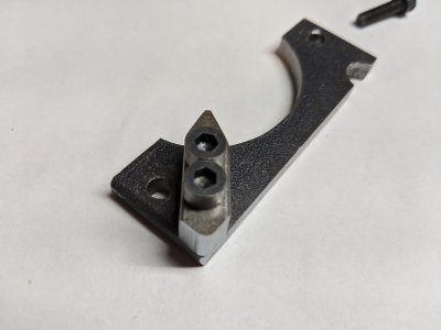
Ok, I was embarrassed about the lathe lock, so worked on it. Turned down the screw heads so they would fit next to each other. Then cut off the key and ground it to the edge of the main piece. Rounded the corner so it wouldn't bite me.
IMG_20200402_181328.jpg
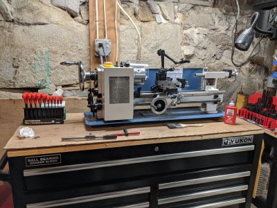
Installed on the lathe. Fits perfectly! Lathe is locked. Someday might make a better key, but this came out well. If the key is removed, the lathe spins freely.
IMG_20200402_181122.jpg
Still pondering how to clamp the handwheel. Need to make some hold downs and spacers. A standard hold down (I have a 3/8" kit) is way too large to fit on the inside of the wheel. 5/16 studs might fit through the undulations in the wheel.
 
Still pondering how to clamp the handwheel. Need to make some hold downs and spacers. A standard hold down (I have a 3/8" kit) is way too large to fit on the inside of the wheel. 5/16 studs might fit through the undulations in the wheel.

You just need to open up the bore right? ......or was it cutting the keyway?
Either way, is there any reason you can't just grab the backside round hub in the 3 or 4-jaw chuck?

-brino
 
@brino, I need to partially bore out the hub. And cut a keyway. I want to sink the shaft into the hub so that the top of the machined spacer is level with the back of the hub.
IMG_20200402_194130.jpg
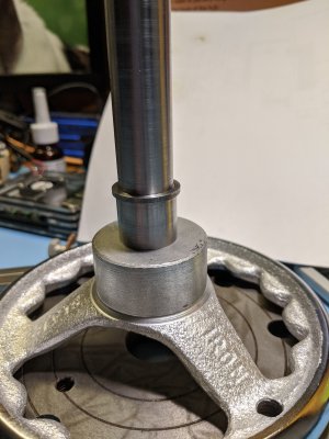
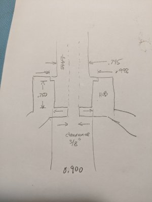
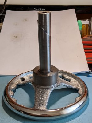
The top diameter of the shaft is 0.795". The ring diameter is 0.998", and the bottom piece is 0.900". (1" stock) The top surface of the ring is to be flush with the hub surface. The ring will retain the key from falling out. I will then cut a key in the hub, and one in the shaft (up to the ring, but not through it). The bottom of the hub has a 1/4" hole, I need to bore it to clearance for 3/8". So I can't simply bore it through from the other side

Here is a simple sketch that I just made. I left out the key. It is cut in the 0.750" diameter section of the shaft and the hub.
IMG_20200402_200037.jpg
All this is to say, that I think it's better to hold the wheel to the plate in this current orientation. I did look at using the jaws of the 3J chuck in an opening fashion. Sorry, I'm at a loss for the right terminology. When I first looked at it, the jaw height wasn't quite high enough to have enough grip. Maybe have to look at it again, to get a different perspective. Perhaps there is a better simpler way to do this. That's why I'm posting.
 
Well, :chagrin:, holding the handwheel was easy. All it took was a night's sleep to figure it out. Switched jaws on the 3J chuck and opened the jaws. The wheel's not quite running true, but it's ok. It was true on initial clamping, but it shifted when I tightened (actually loosened) the jaws. Slight vibration when running. Not quite enough vibration to make me want to balance it.

Bored out the 3/8 clearance hole clear through the hub with a Micro 100 boring bar BB-2301600. Could have used a drill, but I was afraid a larger drill might grab and rip the wheel off the chuck. Cast iron is messy! Lots of little bits of cast iron flying in the air, getting on everything, including my face. Can't wait 'til I hog out the hole, that's going to be a mess! Probably change the bar to a standard boring bar for hogging out. That carbide bar just seems so delicate. It's waiting for me to make a mistake... Back to boring boring.
 
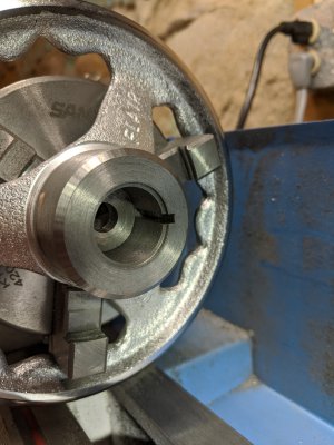
My goodness what a mess. Even after cleaning everything up with a vacuum, things are still messy. I cleaned the ways with a brush, and some wipes, and still the cast iron is everywhere. Next, using the lathe lock, managed to cut a key slot using an 1/8" cut off blade. Each cut was no more than a few thousandths in depth at a time. Sometimes only a thousandth at a time. The lathe carriage handle really doesn't have much mechanical advantage, so it was pure grunt work. Some cuts just really were difficult. About 80 cuts later we have:
IMG_20200403_184329.jpg
That's it for today. Tomorrow the shaft will have a matching slot cut. Then I'll fit the key. The key might need a little polishing to fit, as it is oversized. Dunno why I bought oversized keystock, glutton for punishment?
 
It must have been a pain to get that running true since you had to grab between the handle flutes with the outside jaws on the chuck.
But you did it.

It looks perfect from here!
Nice job.

Thanks for sharing it.
-brino
 
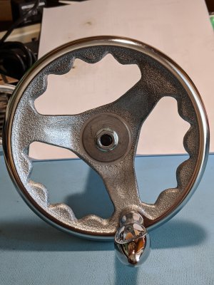
Done with the wheel, save for a little touch up and the right size bolt. The small flange got dinged when it was in the vise to saw. I had wrapped it in tape and used aluminum jaws, but somehow it got damaged. Here's a couple of pics of the handwheel using a 5 inch stud. The stud will be replaced with a socket head cap screw. Have to say, this was an interesting adventure. Cutting keyways by hand is something I'll remember in a less than fond way. The key was oversized, so it had to be lapped and ground it to fit. Can't believe how much time there is in this simple thing.
IMG_20200406_131945.jpgIMG_20200406_132057.jpgIMG_20200406_140605.jpg
Hmm, so where was I?

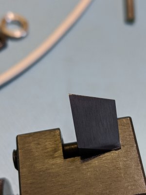
Oh yeah, threading. A new threading tool in HSS was ground, using mikey's angles. Added a flat along the edge. I have some 12L14, O1, and 4140 in the right size. For some reason, didn't get 1144, guess it slipped my mind. Maybe next order. Seems like 1144 would be my best bet for strength + machinability. This pin is in relatively high stress as it is a pump pivot. The pin is held at both ends and the pump arm pushes against the middle. I've had some "commercial" pins bend.

Think I'll practice with 12L14, to get the idea, and eventually make it in 1144.
 
Done with the wheel, save for a little touch up and the right size bolt. The small flange got dinged when it was in the vise to saw. I had wrapped it in tape and used aluminum jaws, but somehow it got damaged. Here's a couple of pics of the handwheel using a 5 inch stud. The stud will be replaced with a socket head cap screw. Have to say, this was an interesting adventure. Cutting keyways by hand is something I'll remember in a less than fond way. The key was oversized, so it had to be lapped and ground it to fit. Can't believe how much time there is in this simple thing.
View attachment 319861View attachment 319862View attachment 319876
Hmm, so where was I?

Oh yeah, threading. A new threading tool in HSS was ground, using mikey's angles. Added a flat along the edge. I have some 12L14, O1, and 4140 in the right size. For some reason, didn't get 1144, guess it slipped my mind. Maybe next order. Seems like 1144 would be my best bet for strength + machinability. This pin is in relatively high stress as it is a pump pivot. The pin is held at both ends and the pump arm pushes against the middle. I've had some "commercial" pins bend.

Think I'll practice with 12L14, to get the idea, and eventually make it in 1144.

Great job WobblyHand! Looks good and I bet it works good too. Really comes in handy when cutting threads with a tap or die.

Roy
 
How close do you need to get to the shoulder? Does the part require no thread relief between the thread & shoulder? With practice you should be able to get it. I can thread into a 1/16" wide thread relief no problem disengaging the half nut without any aid.

By aid what I mean is a dial indicator. When I single point threads I set up a dial indicator to read zero 10 thou off a shoulder or blind hole. I use the modified flank method for threading so to set the dial indicator after setting tool position off the work, I retract the cross slide, advance the compound to the full depth required for the thread pitch being cut, then move the carriage so the cutter bottoms out on the shoulder or the blind hole. Then I set the dial indicator for the carriage +.010. I set the 0 mark at 12:00, the needle starts moving from 6:00 on my DI.

I'm certainly not a pro or even close but I'm able to disengage at 0 on the dial indicator pretty consistently or within a few thou. So in theory I could probably get even close than 10 thou but I never have a need to get that close & to play it safe. Sometimes I thread with no thread relief at all using this method. I know I'm not the only one that uses a dial indicator for threading. Although I have a DRO now, a digital display is pretty much useless for the Z axis for threading.

Threading from headstock to the tailstock is great & allows you to run higher spindle speeds than you normally would & should give you a better surface finish but there are downsides too. Pretty much always need a thread relief which most people use anyway (stronger with no thread relief). But if threading a very coarse pitch the thread dial will be moving pretty fast. There is no room for error engaging the half nut on a specific mark when needed. At least with threading conventionally from right to left you do have room for error & can reset with no damage if you miss your mark. But this shouldn't be an issue once you are used to it. If you are threading a metric thread & you have an imperial lathe (or vice versa) you can't use the half nut here & if the thread is up to a shoulder or a blind hole, getting your carriage lined up for the next thread will be tricky. On top of all that you'll need LH tools. Not knocking the method, just saying it's not for everyone.

View attachment 316720

No thread relief
View attachment 316721
@darkzero ' not sure the method you speak of..ut I wanna know more! Do you need a reverse tumbler to execute what your talking about?
 
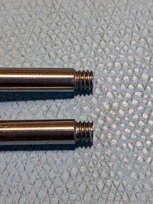
Tried a piece of 12L14 with the handwheel setup. Boy, that handwheel really helped! Made it a lot easier. Was able to make some decent threads. They are better than the originals. They ought to be, since I'm using 12L14. (I bought some more of these pins - got to keep the economy going.) Looking carefully at the originals, it is obvious they were single point threaded. And there is no groove, the threads just start. (Original on top, 12L14 on bottom)
IMG_20200407_182955.jpg
I then tried turning the original 12L14 threads (hex stock - from early in this thread) down and recut them under power. This is with the threading tool I ground. The threads are better quality than with the LMS threading bit, but there are some burrs. Looking carefully at my tool, I see the tip is cracked off. Now, I put in a flat on this tool along the edge. The flat can't be too wide, or I can't do 32 TPI threads.
IMG_20200407_183048.jpg
I seem to be breaking off the tip. What could cause this?

I'd like to make a relief for the thread. What kind of tool is used for this? Could one grind a parting tool thinner? (Have a spare blade) The relief that is there was just keeping the threading tool in the same place, but that doesn't create the square shoulder that it should have.
 
Back
Top