Surface grinder wheel balancing from scratch, and on the cheap:

Several things about this.
I'm pleased for him that he got such a nice finish. What I could see was his surface grinder, or parts of it, moving relative to the background. Maybe all surface grinders do that in the face of reversing inertia, I don't know, but here is the place to ask.

I see the tops of his jig are drill rod, or something like it. Still theoretically a tiny point contact with the round arbor, so minimal rolling friction. It just looks a lot less deadly than the very convenient re-purposed planer blades. If the rails were drill rod, I guess they would have been glued, or secured in some non-distortion way.

I am surprised that it took that much removal from both sides to get it balanced. Of course, the closer to the middle, the less is the stress, offset by the closer to the middle, the more that needs to be removed. I have to say everything in my logic resists drilling out anything, and I remain to be convinced there is not a better way. I defer to those with the experience who can say that drilling on a ringing good grinding wheel is no big deal, and it works just fine.

For a wheel that needs eight chunks like drilled out, it speaks of a wheel that was not so sweetly set concentric to the arbor in the first place!
I have not done it yet, but I think a little calculation of the imbalance plotted vs amount off centre may be revealing.
The same calculation leads inevitably to vibration forces for a given RPM.
Going yet further, it yields the tensile load for a given wheel width and radius.

We only need the first of those. I think that the whole heavy wheel, off centre by even a tiny amount, may be worth a whole lot of drilled hole mass removal. I just don't know yet if this is so. Either way, I so dislike giving a grinding wheel such a focused weak region stress raiser, I would go some way to seeking an alternative. Can one add mass reasonably conveniently?

OK - it's just my opinion, and I don't want to be just an armchair critic. I will have to do something like this soon.
I am happy too be told otherwise from those who know more with some certainty.
 
My weigh scale gadget tops out at 500 grams, and I don't have any spring balance or other handy kit. When it comes to weights of machine stuff, I either find it easy, rate it in grunts+puffs, compare it to 25kg bags of cement, or resort to something with mechanical advantage!

Can someone help with the approximate weight of a grind wheel, and mention it's nominal diameter, width and centre hole?
Thanks

[Edit: I remembered. There is a balance thing in the kitchen with weights, for baking and suchlike. Still a no-go, because if I get busted trying to put anything like a (used) grind wheel from out of the shop on it, there will be hell to pay! ]
 
Last edited:
Ugg... well, I still haven't gotten anything done in a while. We had some family over 2 weeks ago, and immediately after the fires in Oregon started, so air quality outside sucks. Hopefully I'll get back into the shop soon enough to make the arbor/arbor nut.
 
Ugg... well, I still haven't gotten anything done in a while. We had some family over 2 weeks ago, and immediately after the fires in Oregon started, so air quality outside sucks. Hopefully I'll get back into the shop soon enough to make the arbor/arbor nut.
Go a little easier on yourself Erich. You have my sympathies about the fires you folk have to endure.
Human's are smart, and can tell when something is up, even from quite small signs. I happen to be one who thinks the signs are pretty much compelling!

I have also been distracted by domestic stuff, one darn thing after another, ending up this morning with the lady of the house after me to "do something" because of water making it onto the kitchen floor from "somewhere under the sink/ water softener region". Yuk!
Just when I was ready to be sneaking off to where the machine stuff with the nice aroma resides!

I know that when you get the arbor together, you will let us know. When you actually grind a surface, rub it over with a stone that has been rubbed against another (stone), reveal the pattern, and take a picture. Meantime, I will attempt the calculation about off-centre balance. I still have pretty much big negatives about drilling eight chunks, four a side, dead opposite each other, into a ringing wheel.
 
Alright, a little progress on the arbor! I am going to the calculations I made in my drawing, at least where they are important.


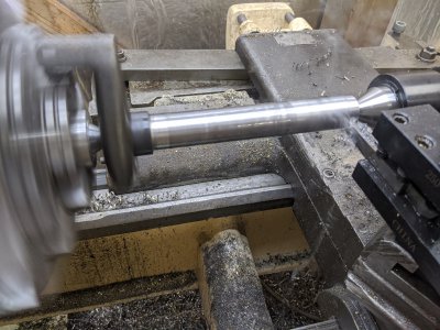
I'd already put centers in each end, so the first step was to turn it down to roughly 1" all the way across. I obviously couldn't get that last section under the dog, but that is not going to matter since I'll get it when I flip it around.

MVIMG_20200922_134336.jpg
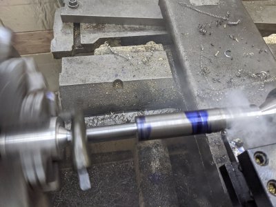
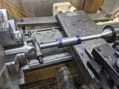
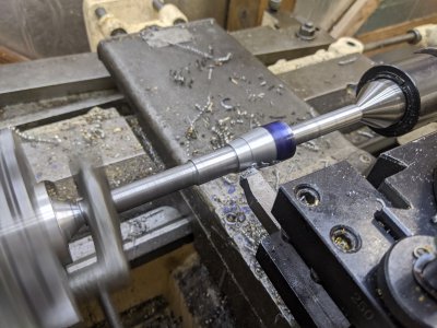
The next step was to turn each 'end' down to a rough dimension. I'm going for .500, and I don't want to change my cross-slide/compound when I go to cut them (basically, don't change my setup if at all possible to make them the same!), so I cut each down to ~.515, which is enough to get the threads done, and still enough that I can take that cut without deflecting the tool too much. Since I'm between centers, flipping it around is trivial enough. I got the center-section set to the right 'width' here as well:

IMG_20200922_141852.jpg
IMG_20200922_143006.jpg


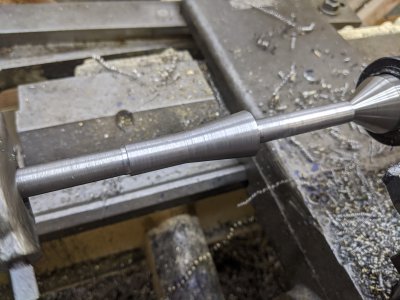
Next, I wanted to separate the threaded section, so that I could cut the taper. So, I turned that down to a touch under .625 (book says .6239) with a left-to-right tool (never remember which is which...) in prep for 5/8-18.

IMG_20200922_144542.jpg


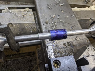
Next, I cut the taper. I'd previously indicated-in my taper attachment, so this was as easy as tightening 2 bolts, and going to town! I used the power feed + the same tool (left to right) and cut until the dykem from above was removed and so that the 'intersection' was about right. I'd chamfered the end just a little to get rid of the burr, and put a little slot in the transition for my threads to start.

MVIMG_20200922_144943.jpg
IMG_20200922_145530.jpg


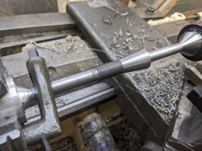
Finally, I cut the threads. I have a 'stop' built into my lathe, which is super handy so I used that, then used the compound for a 29.5" infeed. I did a scratch pass, and realized I was WAAYYY off! I was at 13 TPI, not 18! Turns out, I'd read the 'Thousandths-per-rotation' chart instead of the 'Threads Per Inch' chart. Fortunately, I checked after my scratch pass to make sure.

I used an indicator to get my .034 DOC over a few passes. The tough part was that I was starting from a single-point spot between the two sections, so I had to make sure I hit my thread dial EVERY time! There was no chance to stop/restart if I messed it up. Fortunately, it went right! I cut to my DOC using the indicator, then used my thread pitch mics to confirm, then used my thread-wires to confirm again. All seem right at the top of the range.

I'm going to make my nut separate, so I can fit that to the threads.

IMG_20200922_153520.jpg

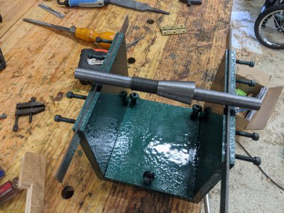
I have 2 more ops left, turn the 'right' side down to final dimension, then, without moving the cross-slide, flip the part and do a single more cut there. Then, I'll consider this part done, and I can move onto the nut!
 
My wife had a few things she wanted to do the last few days, so I only got about 2 hours the last 3 days. SO, I didn't snag many good pictures.

First step was to cut the 'long' pieces down to 500 thou (actually ended up about 2 thou under). I started on the 'thicker' side, and did 1 cut plus a spring pass. Then, without moving the compound, flipped the part around between centers, and cut the other side + a spring pass:

PXL_20200925_215155260.jpg

TODAY, I built a nut for it out of aluminum, I did a knurled outside (a hex seems like it would not be balanced), and single-point threaded the inside. The 1.5" long threads ended up being too long, so I cut the nut down to ~1", and 'counter bored' one side about 1/2". I'll still have about 1/2" of threads, so that should be fine.
 
I’ve spent way too many days overbuilding stuff ( tools) that really doesn’t need to be heavily built.
I’m now of the mindset...KISS
anyway...not knocking your build. It’s a well done balancer. And if that’s what floats one’s boat...more power to you.
That said... here’s the balancer I’ll build when I need one. It’s really simple.
Grinder wheel balancer

I'd actually seen that one when I was researching how to do this one. I liked the JB Weld trick on the surface plate, but wasn't confident enough in my ability to get it right 'the first time'.

That said, your balancing replacement nut is almost exactly what I'm going to do! I'm likely going to modify the 'factory' nuts instead of making new ones, but thats about exactlly what I'm going with. What lead you to choose 5/16-18 if I can ask?

Side note: Thats a fantastic looking Burke Millrite! I've got one of the first powermatic ones, but mine spent a long difficult life in a high-school, so its not nearly as nice as that one.
 
Eric, don’t get too envious. I didn’t overpay for my Millrite but it surely wasn’t pristine. I had to do a good bit of work on it. I had to replace the spindle bearings and when I got in there, I found out they were already replaced. To make matters worse, I had an odd issue in which the quill was kind of flopping around ... moving in and out about an 1/8” . Lots of signs of metal worn out where the bearings seat inside the quill/ spindle.
I seem to have fixed it and it’s holding up, but I was really concerned that maybe my mill was toast. But, as I always say.... I’d rather be lucky than good. And I lucked out because it’s holding up well. Then I attempted to regrind the spindle r-8 taper. I had a lot of runout or whatever it’s called. My collets were micing something like 8 thousandths out. It’s now about 2 to 3 thou out now.
And... it looks good because i repainted it. But it’s good now and I like it.
Maybe one day I’ll try to hard turn it to get it closer to zero.
 
Last edited:
Eric, don’t get too envious. I didn’t overpay for my Millrite but it surely wasn’t pristine. I had to do a good bit of work on it. I had to replace the spindle bearings and when I got in there, I found out they were already replaced. To make matters worse, I had an odd issue in which the quill was kind of flopping around ... moving in and out about an 1/8” . Lots of signs of metal worn out where the bearings seat inside the quill/ spindle.
I se to have fixed it and it’s holding up but I was really concerned that maybe my mill was toast. But, as I always say.... I’d rather be lucky than good. And I lucked out because it’s holding up well. Then I attempted to regrind the spindle r-8 taper. I had a lot of runout or whatever it’s called. My collets were micing something like 8 thousandths out. It’s now about 2 to 3 thou out now.
And... it looks good because i repainted it. But it’s good now and I like it.
Maybe one day I’ll try to hard turn it to get it closer to zero.
Ah, I was lucky that after replacing my spindle bearings that it is in great shape. My ways on the other hand are toast, particularly on top of the knee, but the X axis is bad too. If I get the gibs tight enough to remove excessive "twist" of the x axis, I lose about 6" of travel at both ends.

Plus my table is rough. I spent a while at one point with some flat stones so it isn't too bad, but I'm jealous of your flaked top :)
 
Back
Top