Surface grinder wheel balancing from scratch, and on the cheap:

I have seen two reasonable (to me) approaches to balancing a grinding wheel. One uses an arbor with holes in a circular pattern where weights can be installed. The other uses a two-piece arbor with a channel inside, and free-to-move bearing balls are placed in there. The latter is a kind of dynamic balancing system, while the former is a static one.

An online search will find numerous examples of both of these as a DIY.

Neither of these will address a wheel that wobbles. My impression is that most problems can be addressed by the static or dynamic balancing schemes, along with dressing the wheel.

I have read of folks balancing wheels by removing material but that scares the heck out of me! I DO like the idea of using something like epoxy but I'm not sure how you'd apply it. OH, now I get it -- use epoxy putty....it cures fairly slowly so you could adjust the balance. Hopefully it sticks well enough, eh?
 
I have not the kit to be balancing stuff (yet), but I know I am going to have to do all this - so I think it through.
Start with a notional grinding wheel. Let us take these on one at a time.

1. First location on the shaft.
The "hole" is bigger than the shaft. It can be a bit this way or that, regardless the internal non-uniform weight balance.
It is held between "blotting papers", presumably to spread the clamping force from six highly stressed local contact points.
The disc of the wheel besides being eccentric, may also not be perpendicular to the shaft. You could "make it so" by dressing the sides, and rim, to in effect "carve out" a smaller concentric wheel out of the bulk of the starting wheel.

2. Radial balance
This would be the weight distribution that makes it "roll" on the jig. If this balance is fixed first (by one of several methods), it all gets undone by the first dressing. It becomes physically perfectly circular at the rim, despite that it was caused in the first place by the whole disc not being concentric on the shaft, but clamped between the "blotters". Only the outer rim is circular. The hole in the middle is eccentric, and there is now more weight on one side. Start again! The wheel has to be such that repeated dressings are not going to make it go unbalanced.

I think the wheel densities just might be a bit better than we credit them for.
Saying that repeated dressings which require regular re-balancing is inevitable, and blamed on "non-uniform density" within the wheel, may be wrong. It might well be partly down to internal non-uniform densities, but clearly, repeatedly dressing the outside of a balanced wheel to make it circular, when the centre hole is even slightly not in the middle, will make it go unbalanced about the axis. This with a certainty that is way more inevitable than unknown internal non-uniform densities being removed from the rim in tiny amounts.

3. Axial balance.
Even if you balance a wheel (several methods), such that it won't roll on the blades, and even if the density through the wheel was supplied by the perfection fairies and elves, if the wheel disc is not physically at right angles to the shaft, (i.e. swash-plate wobble), there is a problem, though less than we might think. Relative to the axle, there is no theoretical acceleration of masses back and forth along the direction of the axle.
There is an axial "scrubbing motion. Except for a blurred look, in theory, it spins OK - that is until the first attempt to dress the side.
Even the smallest change to one side that is not replicated on the other will bring about the Father and Mother of axial vibration! Remember, we started with a balanced swash-plate!

At the least - for that reason, I have to read again the virtues of the kineticprecision.com kit. I suppose they are experts, and they have it all figured out. It's just that I haven't fully understood what they do. Adding a ring clamped to the wheel, so to become part of the wheel. with ability to add weights in the form of grub screws seems to be what they are up to, and an obvious way to balance without drilling, nor adding material (except grub screws).

Dynamic axial balance
There is also the need to discover and compensate for a weight to one side of the wheel, somewhere in it's disc. This weight may be be compensated for to stop a roll on the jig, but slings back and forth along the axis. There are good tricks to compensate this also, some of them exotic. A quick 'n dirty I once tried with a car wheel was to suspend it from centre like a plumb bob, and set it spinning. I have no idea if this would work on a little grinding wheel.

4. About swash-plate adjustable rings.
An old and effective idea. Replace the blotter compression big washer discs each side with two stacked together. They be thicker to accommodate that they have a tilted side each. I am sure one could make a pair by turning them, then grinding off one side of both set down together, at a few degrees tilted. Tilted sides placed together, so they cancel, then rotated relative to each other up to a desired tilt. There needs to be some way of rotating them..

a) Relative to each other, to adjust the amount of tilt, and ..

b) Both together relative to the grinding wheel, to put the tilt in just the right place to take out the wobble.

I think there needs to be a matching pair put on the other side of the grinding wheel, set 180° relative the those on the other side.
With all this, we have a nearly straight wheel, that is in with a chance.

Only now, after dressing, the arbor stays with it, and we get to balance it. If the centre hole is reasonably on the axis, you can likely dress again, and keep dressing, until either centre eccentricity, or internal non-uniformity, or a combination of both, catches up with you.

If I got this wrong, let's hope I discover what really happens soon.
 
SO, I got a few hours in the shop, and I have some progress!

For the life of me, I couldn't find the old blades to my 6" jointer, but I DID find my 18" planer blades :) I spent a few minutes with some scotchbrite and a stone cleaning them up. They were covered in a lot of wood pitch, so windex helped with that. I didn't bother cutting them down yet, but I will eventually...
IMG_20200829_114111.jpg

First, I drilled 5 holes for the set screw. Why 5? Because I had 10 bolts! In retrospect, I'm probably going to shorten or buy much shorter ones, but 10-32 bolts seemed fine for now. This was the most time consuming part, because for some reason despite drilling/milling reasonably well, this material seems to tap terribly.

IMG_20200829_122055.jpg

I have a 1/8" cutter that I made an arbor for a few months ago, so I cut a 500 thou deep slot down the side. The blades fit in a little tight, but loose enough I can slide them with my hand. I figured thats a good fit, and I can find a thin stone for the inside of the slots if I need to make it better.
IMG_20200829_123759.jpg

I did those steps 2x. However, the 2nd one came out worse due to 2 mistakes:
1- I messed up one of the bolt hole locations. They are .300 off the side, and located at 2.500, 1.250, 0, -1.250 and -2.500 on the Y axis as cut. I messed up and drilled one of them at 1.500 instead of 1.250, so its a 1/2 inch off.
2- I forgot to tighen my quill until the slot cutter was already about 1/4 of the way. By the time I noticed, it had 'climbed' 50 thou, so the slot is 50 thou off center.
However, neither of those problems are a deal-breaker for a shop-project, so lets keep going :)

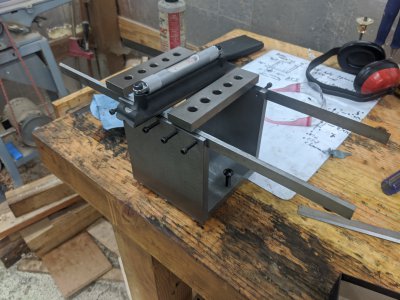
This is how I got the blades co-planer (also, you can see how ridiculous 18" blades are:)). I tried putting a stack of blocks inside and then getting the blades level from there, however I found that just putting the blades straight down on the surface plate, then tapping them with a lead hammer got me perfect contact all the way across! Because of this, I'll likely leave them ~2-3" over-length when cutting them to make this part easier (likely, just cut an 18" in half :)).
IMG_20200829_133830.jpg

Finally, I leveled it on my bench to see how the adjustments worked. I used a pair of parallels to do the other direction, and just my 8" starrett (bought for this purpose, and likely about 75% of this project's cost!) for the other. First I leveled it with the 2 on the same side, which went really quickly. I found myself happy I used the fine thread (3/8-24 I think!), as it made dialing it in simple.

Then, I put the parallels on, and flipped the level the other way and leveled it in that direction with the other screw. I confirmed back and forth with the level in both directions, and is dead-on!

Overall, leveling took ~45 seconds. It took longer to find my level :)
IMG_20200829_134102.jpg

I think i've still got 3 things left to do on this :

1- Paint! I have some blue and orange somewhere, as well as some green hammerite. I hope I can find the latter, and paint it with that.

2- Cut the blades down. I think I can just use my cut-off wheel and cut 1 of the 3 blades in half and be perfectly happy here. ~8.5" seems about perfect, the overhang will give me plenty of room to tap them for co-planer reasons.

3- Made some sort of blade-guard. I might just do this with some spare oak, but this thing looks like a death machine while in storage. I think I'll just grab some wood scraps and make something that fits nicely over the blade.
 

Attachments

  • IMG_20200829_134058.jpg
    IMG_20200829_134058.jpg
    3.6 MB · Views: 20
Unless you propose to stash the Starrett somewhere, and never use it again, don't put the cost of the Starrett entirely on this project. :)
 
I have not the kit to be balancing stuff (yet), but I know I am going to have to do all this - so I think it through.
Start with a notional grinding wheel. Let us take these on one at a time.

1. First location on the shaft.
The "hole" is bigger than the shaft. It can be a bit this way or that, regardless the internal non-uniform weight balance.
It is held between "blotting papers", presumably to spread the clamping force from six highly stressed local contact points.
The disc of the wheel besides being eccentric, may also not be perpendicular to the shaft. You could "make it so" by dressing the sides, and rim, to in effect "carve out" a smaller concentric wheel out of the bulk of the starting wheel.

2. Radial balance
This would be the weight distribution that makes it "roll" on the jig. If this balance is fixed first (by one of several methods), it all gets undone by the first dressing. It becomes physically perfectly circular at the rim, despite that it was caused in the first place by the whole disc not being concentric on the shaft, but clamped between the "blotters". Only the outer rim is circular. The hole in the middle is eccentric, and there is now more weight on one side. Start again! The wheel has to be such that repeated dressings are not going to make it go unbalanced.

I think the wheel densities just might be a bit better than we credit them for.
Saying that repeated dressings which require regular re-balancing is inevitable, and blamed on "non-uniform density" within the wheel, may be wrong. It might well be partly down to internal non-uniform densities, but clearly, repeatedly dressing the outside of a balanced wheel to make it circular, when the centre hole is even slightly not in the middle, will make it go unbalanced about the axis. This with a certainty that is way more inevitable than unknown internal non-uniform densities being removed from the rim in tiny amounts.

3. Axial balance.
Even if you balance a wheel (several methods), such that it won't roll on the blades, and even if the density through the wheel was supplied by the perfection fairies and elves, if the wheel disc is not physically at right angles to the shaft, (i.e. swash-plate wobble), there is a problem, though less than we might think. Relative to the axle, there is no theoretical acceleration of masses back and forth along the direction of the axle.
There is an axial "scrubbing motion. Except for a blurred look, in theory, it spins OK - that is until the first attempt to dress the side.
Even the smallest change to one side that is not replicated on the other will bring about the Father and Mother of axial vibration! Remember, we started with a balanced swash-plate!

At the least - for that reason, I have to read again the virtues of the kineticprecision.com kit. I suppose they are experts, and they have it all figured out. It's just that I haven't fully understood what they do. Adding a ring clamped to the wheel, so to become part of the wheel. with ability to add weights in the form of grub screws seems to be what they are up to, and an obvious way to balance without drilling, nor adding material (except grub screws).

Dynamic axial balance
There is also the need to discover and compensate for a weight to one side of the wheel, somewhere in it's disc. This weight may be be compensated for to stop a roll on the jig, but slings back and forth along the axis. There are good tricks to compensate this also, some of them exotic. A quick 'n dirty I once tried with a car wheel was to suspend it from centre like a plumb bob, and set it spinning. I have no idea if this would work on a little grinding wheel.

4. About swash-plate adjustable rings.
An old and effective idea. Replace the blotter compression big washer discs each side with two stacked together. They be thicker to accommodate that they have a tilted side each. I am sure one could make a pair by turning them, then grinding off one side of both set down together, at a few degrees tilted. Tilted sides placed together, so they cancel, then rotated relative to each other up to a desired tilt. There needs to be some way of rotating them..

a) Relative to each other, to adjust the amount of tilt, and ..

b) Both together relative to the grinding wheel, to put the tilt in just the right place to take out the wobble.

I think there needs to be a matching pair put on the other side of the grinding wheel, set 180° relative the those on the other side.
With all this, we have a nearly straight wheel, that is in with a chance.

Only now, after dressing, the arbor stays with it, and we get to balance it. If the centre hole is reasonably on the axis, you can likely dress again, and keep dressing, until either centre eccentricity, or internal non-uniformity, or a combination of both, catches up with you.

If I got this wrong, let's hope I discover what really happens soon.

I think you're putting more thought into this than necessary, I think what you call 'radial' balance is the only one that really has an effect. In fact, even THAT only matters when dealing with wheels greater than ~5-6 inches in diameter. Typically people just skip doing it on anything smaller.

#1 is handled by dressing the wheel, as is #3 if it ends up being important. The "wobble" in that way is minor enough (particularly with well made wheels) that I don't think people tend to worry about them.

For #4, The nice part about the blotters is that they are compressable, so you get greater hold. Using any sort of metal washer is typically going to be worse off.

That said, thats based on my minor-understanding of the process. Someone like benmychee or others can correct us :)
OK - I can also be practical.
Fully understanding something is not overthinking it when in practice, one does just enough of what it takes to get it to work.

My whole point was it is that the act of dressing the wheel, making it "circular", is what puts it out of balance, and makes all the balancing work moot, if what it started with was a weights-compensated, fully balance wheel with the central hole even slightly off the middle.

I use the terms "radial" and "axial" to differentiate the directions in which the wheel shakes.

I just love your really serious lead "adjuster" :)
 
Perhaps the wrong word choice... More meant that from a practical perspective, only the 1 direction matters. From a truely practical perspective, even that one doesn't matter for a hobbiest like me :)
 
So I spent the last 2 days learning FreeCAD (I'd previously only done mechanical drafting in 7th grade, and typically my drawings are on a piece of scrap paper or white board!). So, Attached!

For the drawing, the conversion to PNG from SVG messed up, but I don't care enough to look closer :)
 

Attachments

  • grinder-arbor.jpg
    grinder-arbor.jpg
    89.1 KB · Views: 25
  • grinding-arbor-drawing.png
    grinding-arbor-drawing.png
    115.6 KB · Views: 26
How will you use this?

The axle resting on the top?

Must be perfectly level to work.

Real unit is similar except it has a pair of overlapping wheels on the sides that allow the axle to rotate in place.

Need 4 ball bearings like 38KDD, then bolt to opposite sides of each wall.

Sent from my SAMSUNG-SM-G930A using Tapatalk
I've seen that style as well, but I'm trying to emulate the sopko version: https://www.mscdirect.com/browse/tnpla/65107047

Here is someone balancing the same way:
 
Back
Top