

- Joined
- Nov 27, 2012
- Messages
- 7,856
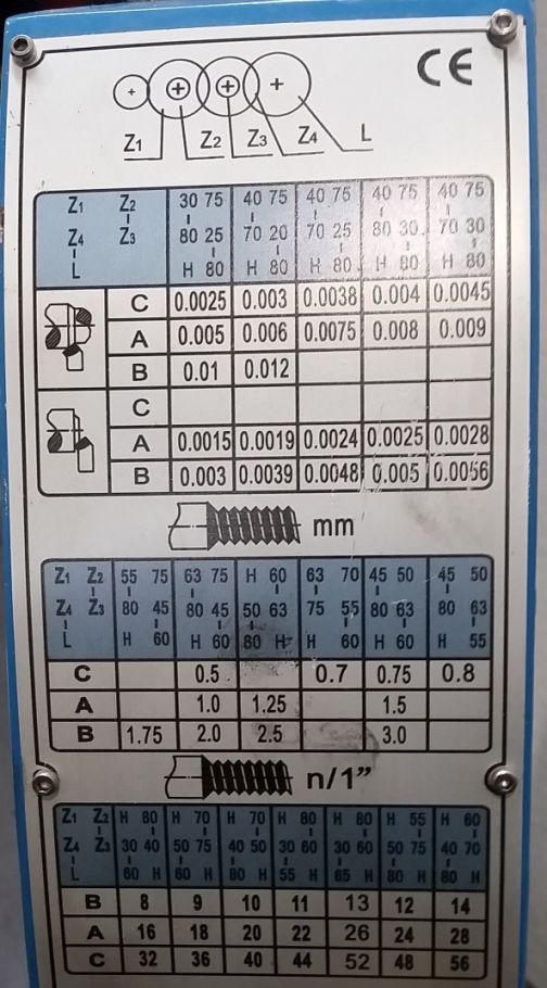
This is what's on the lathe itself. What's the top box for? If the middle is metric, the bottom box is inches, what's the top?
Ok, that's better, I'd follow the chart on your lathe instead of the manual. As I said above I don't understand why there are 2 gear combos with the same lever position for 1.25mm pitch in the manual.
In my post above, follow the gear combo in the second pic as that's what matches the chart on your lathe.
The top section is for feed rate in inches (used for roughing & finishing passes). When you hear IPR (inch per revolution of the spindle), that's what that is. The first 3 lines are feed rates for the carriage. The next 3 lines are feed rates for the cross slide.
So starting from the top for 1.25mm...
60T on the inside/right side, spacer on the outside/left side.
63T on the inside, 50T on the outside. 63T meshes with the 60T.
Spacer on the inside, 80T on the outside. 80T meshes with the 50T.
Lever on position A.
")

