Tube Polisher....

Thanks for sharing, if all this were simple, then everyone would be doing it.

While it is nice to have a cutting tool, a larger diameter tool would help a lot in the process. I might be inclined to make a tool and use a fly cutter. As it may provide much more stability. But I have a tendency to make do with what I got for two reasons, one I am cheap and second I hate to wait. It works a good amount of the time and the rest, well a dismal failure is the polite version.
You are 100% correct, a larger diameter tool would be very helpful. I thought about making a tool, or even re-grinding a router bit or threading cutter. I was just too lazy to do it. I could buy this one off the shelf and get it in a few days. It sat on my desk for 2 weeks before I was ready to do that operation anyway, so time was not a factor. If my local tool grinding genius hadn't closed up shop, I might have had him grind a special tool for me.

Most times things work as expected, sometimes not so much. :) That is the learning experience.
So true.
 
I started to work through the cutter’s speed and feed info as an exercise for my own benefit. Makes the IRS forms/rules look easy.
 
I like that one benefit of having a CNC mill is the ability to take more naps :) Not so sure about the mowing the lawn thing, but that's why I have children..
 
I like that one benefit of having a CNC mill is the ability to take more naps :) Not so sure about the mowing the lawn thing, but that's why I have children..
Well I got the lawn mower from the shed and almost into the shop before it ran out of gas. Then checked my gas cans, empty of course. :rolleyes: So put the lawn mower battery on the charger, and watched my mill make chips because I wasn't ready for a nap yet. That was pretty much like watching paint dry. Maybe the lawn will get done tomorrow.
 
I started to work through the cutter’s speed and feed info as an exercise for my own benefit. Makes the IRS forms/rules look easy.
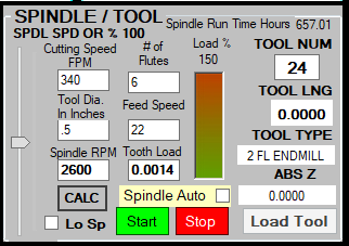
I have this handy feed & speed calculator built into my software. Can be used as a calculator when the spindle is not running, and shows the feed & speed in real time when the spindle is running. Makes it pretty easy to set up what you want. The FPM and Tooth Load are the most important. Given that I am cutting aluminum with a carbide tool, the FPM could have been a lot higher, but I limited it to the RPM that I was willing to run my spindle at for an extended period. So in this case the Spindle RPM vs. the Tooth Load dictates the Feed Speed in IPM. I like to keep the tooth in the 0.001'' to 0.002'' range for most operations.

Here are the cutting parameters I came up with.
1656262383292.png

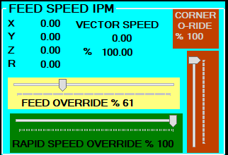
Now the fun part is that since I am feeding with a rotary table, rather than a straight vector sum, the Feed Speed is a little more complex. I'm working on the OD of a 20'' part, so a circumference of ~63'', so to achieve 22 IPM, it has to turn at roughly 0.3 RPM or roughly 1.8 deg/sec. I could have done the math and calculated the feed speed in pulses/second, converted to IPM and then plugged that number into the G code as a feed speed. But I'm lazy so I just plugged 10 IPM into the G code, which I knew from experience was a little fast. Then ran the RT and measured the OD speed with my Shimpo tach as I adjusted the feed speed slider on my screen.

1656264615265.png

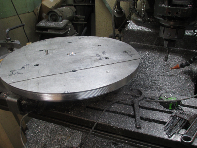
About 3.5 hours later the operation is complete.

1656266218533.png

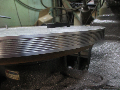
That top groove is a little screwed up, the tool slipped in the holder and tried to work its way down a bit. Not sure how that happened. Not a big deal, but a bit frustrating.
1656266283096.png

I think I'll take the day off, forecast to be about 100 or so today. :faint: I'll stay cool and drink lots of iced tea. :) I'll think about mowing the lawn tomorrow.
 
I'm working on the OD of a 20'' part, so a circumference of ~63'', so to achieve 22 IPM, it has to turn at roughly 0.3 RPM or roughly 1.8 deg/sec. I could have done the math and calculated the feed speed in pulses/second, converted to IPM and then plugged that number into the G code as a feed speed. But I'm lazy so I just plugged 10 IPM into the G code, which I knew from experience was a little fast.
I missed something there, probably because I don't know G-code. What basis (diameter?) is the G-code using for turn rate on the rotary table? You imply you don't enter RPM, but IPM. Sorry if this is a novice question, I have ambitions of getting into CNC at some point, but that has not yet happened.
 
I missed something there, probably because I don't know G-code. What basis (diameter?) is the G-code using for turn rate on the rotary table? Sorry if this is a novice question, I have ambitions of getting into CNC at some point, but that has not yet happened.

This value would normally be calculated by the CAM software as a function of the tool path at a particular radius from the RT center, assuming the CAM software is capable of doing a 4 or 5 axis toolpath calculation. Since I do not have the 5 axis plugin for Fusion 360, the CAM software can not calculate the feed speed.

Also, the CNC software would have to be capable of using the CAM generated feed speed to achieve to correct speed, which mine can not do. I use it so infrequently that I haven't bothered to add that feature to my software.

In my CNC lathe software I do have that feature built in where I can maintain a constant cutting speed in FPM, based on the part diameter. And the CAM software can specify RPM or Constant Surface Speed, specified in FT/Min. Using constant surface speed means that the spindle speed is constantly changing, within a minimum and maximum limit, based on the tool X position. The math is a little crazy, and updates the spindle speed every 5ms.

In this case I just hand wrote the G code for this operation, and did a quick back of the napkin calculation to get somewhere in the ballpark. Then did the final adjustment with the feed speed slider. In this case, 22 IPM on the circumference of the 20'' part, equates to about 6 IPM for a normal X/Y vector move. So in the G code below, after adjusting the speed override slider, the Y moves were actually made at about 6 IPM rather than the 10 IPM as commanded in the G code.

(GROOVE 1, PASS 1)
G0 X10.213 Y-1.850 Z0.6 ( G0 'rapid' move to start position)
G0 Z-0.112 (rapid down to 0.100'' above working height)
G1 Z-0.212 F10. (G1 'normal cutting' feed down to working height, Feed = 10 IPM)
G1 Y0.0 A-90.0 F10. (lead in move, feed Y to 0 while rotating to 90 deg on the RT, makes a nice smooth entry into the cut)
G1 Y0.0 A-450.0 F10. (main cutting move, rotate an additional 360 deg at the set feed rate)
G1 Y1.850 A-540.0 F10. (lead out move, rotate an additional 90 deg while moving Y out of the cut)
G0 Z0.6 (rapid retract Z to a safe height)

Rinse/repeat

I hope that all makes sense :)
 
Last edited:
Back
Top