Tube Polisher....

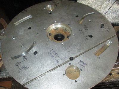
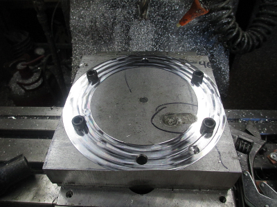
OK, the disk is finished.

Side 1
1657390155218.png

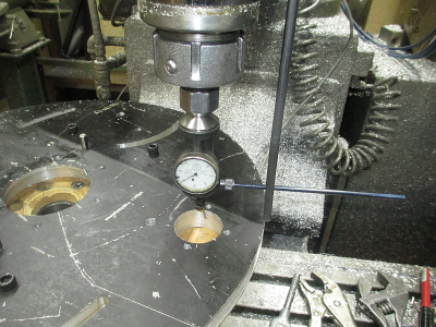
And the back side. The only work on this side is the pockets for the drive roll bearing retainers. So flip the part over using the dowel pins to align it. Then double check the alignment with the Blake. It was off a couple thou, but that's the reason we double check. No problem, just reset the position in the computer and make chips.
1657390261735.png

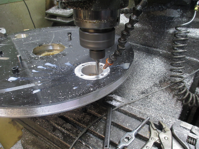
Then machine the pockets
1657390533859.png

The disk is complete, and the rotary table can come off of the machine.

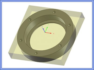
Next is the main bearing retainer. I need to scrounge up a chunk of 6061, 6''x6''x1'' I'm sure I have something on the shelf.
1657390840453.png
 
OK, moving right along, the bearing retainer.


Found about a 24'' square x 1'' aluminium on the shelf. Grabbed a 6 x 6 chunk of it.
1657507325201.png

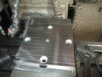
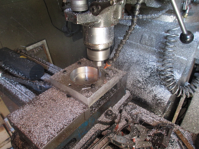
And found a 6 x 6 x 1/2 chunk on the scrap shelf to use as a fixture plate, was a fixture for another project. Mounted it up in the vice and faced it off.
1657507479986.png

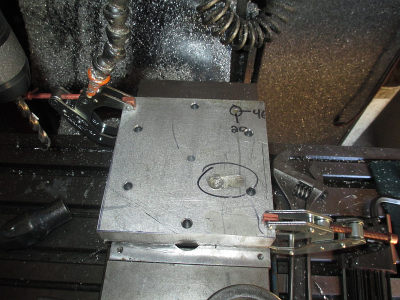
Drilled & tapped the fixture plate and drilled the work piece to match.
1657507582592.png

Did a quick facing skim cut, about 0.005'' just to flatten it out.
1657507699552.png

Then bolt down and remove the clamps. Run a quick air cut to make sure the tool will always clear the bolt heads.
1657507840953.png

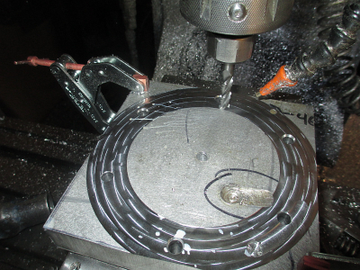
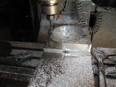
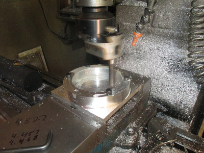
Rough pocket the center, 10 IPM, 2400 RPM, 0.0015 chip load, 0.050 stepover, 0.895 DOC
1657507985780.png

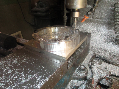
Then rough out the outside.
1657508216517.png

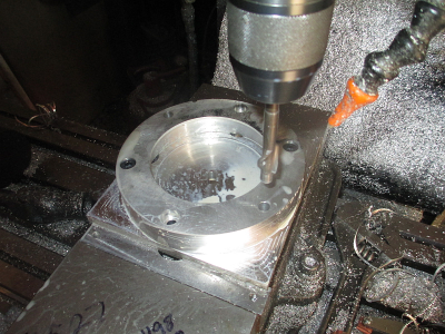
And a finishing pass, helical down cut, about 0.25 down per rotation.
1657508297868.png

Then bore to finished size for a good bearing fit. 4.5'' is about the limit of my boring head with the tool vertical. :cautious:
1657508643489.png

Then flip the part over and counter bore the screw holes 0.350'' deep.
1657508956731.png

And done!
 
For the next installment, the Tensioning Arms.
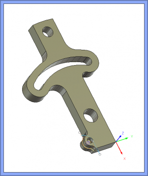
1657594612098.png

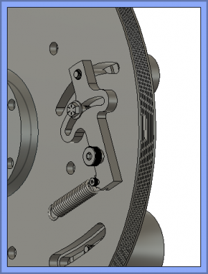
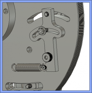
This is where they go on the assembly
1657594843438.png

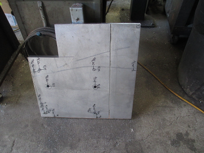
We had these laser cut, we can't machine them as cheap as getting them lasered. The hole locations are somewhat critical, so no holes were lasered.

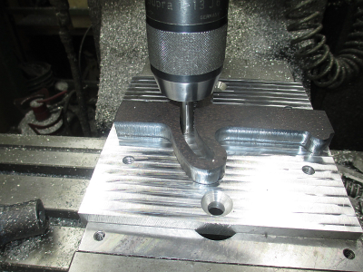
Starting with the fixture plate that was already in the vise from the bearing retainer above. Face it off and drill & tap a 3/8-16 hole about there, anywhere close is good enough.
1657595186606.png

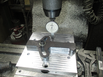
Then dial in the part in the X axis

1657595286225.png

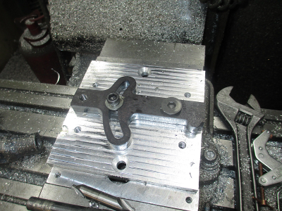
Locate the corner for the X/Y coordinates and drill & tap/ream the holes as needed. I guess I never got a picture of the clamp on the right edge, I left that in place until I drilled & reamed the 5/8 hole then I could remove the clamp and drill the spring attachment point.

1657595592845.png

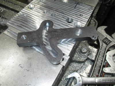
And done with the holes.
1657595700809.png

The next operation will be to cut the slot in the spring attachment point. That is going to be fun, 0.130 wide x about 0.500 deep with a ball end mill. Tomorrows project, I'm hot & tired. :faint:

1657595908355.png
 
Really taking shape. Well done.

Was looking at the application of this tension arm on the original assembly. Will you be able to apply enough tension with the short leg of the lever where the spring attaches?

Also, how are you handling aligning the belt drive wheels to ensure belts will track correctly? Didn't see any in the assembly drawing.

Thanks very much for sharing your build. Love watching a plan come together.
 
Was looking at the application of this tension arm on the original assembly. Will you be able to apply enough tension with the short leg of the lever where the spring attaches?

Also, how are you handling aligning the belt drive wheels to ensure belts will track correctly? Didn't see any in the assembly drawing.

Centrifugal force is the main tensioning action, the spring just applies a pre-tension.

I'm hoping the crown on the drive pulleys will do the job. :cautious: If not, I'll have to figure something out. :rolleyes:

Thank you for the kind words.
 
Centrifugal force is the main tensioning action, the spring just applies a pre-tension.

I'm hoping the crown on the drive pulleys will do the job. :cautious: If not, I'll have to figure something out. :rolleyes:

Thank you for the kind words.

I didn't take into account the centrifugal force of the backing plate. The longer lever of the tensioner will definitely add to that force.

Assuming that everything aligns properly the crown should, but may be an issue as the woven belt becomes used.

I tend to over think things and too often over build to account for issues that could be.
 
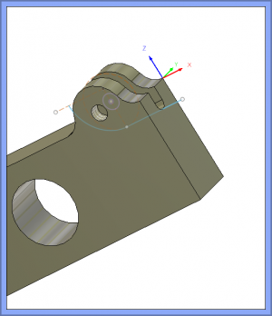
I decided not to cut the slot for the spring and am going to just use a bit longer shoulder bolt, and slip the spring over it.
1657935899142.png

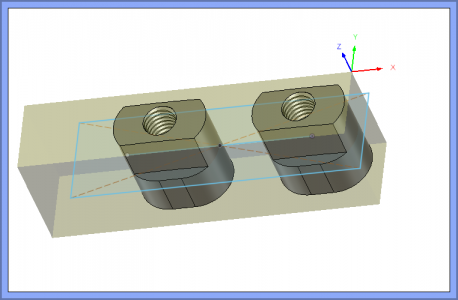
So the next project was the T-nuts
1657936152485.png

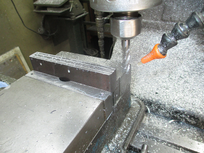
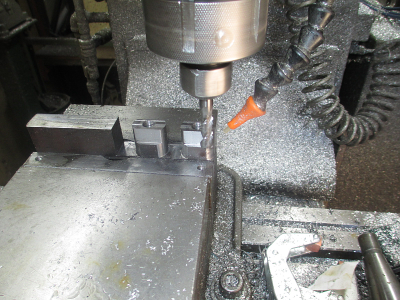
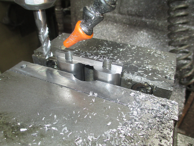
Start out with a 1 1/4 X 3/4 X 6 chunk of hot rolled something steel, face it off, drill & tap, and then start chewing. 3/8, 3 flute carbide aluminum rougher ( yeah, I know I shouldn't use it on steel) 0.500 DOC, 0.035 engagement, 165 FPM, 1680 RPM, 8 IPM feed. About 34 minutes of run time.
1657936207755.png

I switched to a finishing endmill and made a helix path cleanup to size.
1657936294602.png

Face the excess off of the back

1657936349243.png


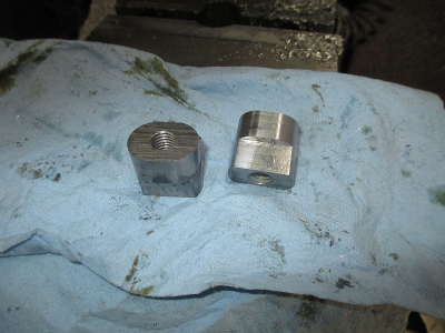
And done.
1657936393491.png
 
I think the extended shoulder bolt for the spring is a much better idea. It retains the strength in the part and less of a headache.

Nice work on the T-Nuts. Do those require a radius to run in a slot? Don't see where they are going.
 
Back
Top