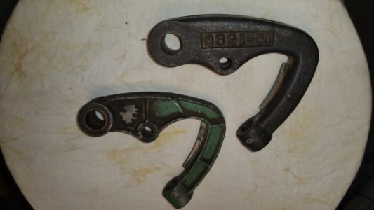
Here's something I've been working on for a bit. Didn't do any machining on it today (yesterday, yes) but took the photo today. While it's one of the more precision things I've done as a relatively inexperienced machine-er (I won't claim the title of 'machinist') it is far from much of what I've seen here. In my defense, it's an idea being explored -- revealing a number of shortcomings, some obvious some not-so. I don't want to engage in a "what is it" quiz because that would likely degrade pretty quickly. So, the reveal is: it's an experimental sine table combined with a shallow-jaw vise so I can machine some tapers for yet another experiment.

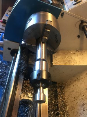
The sine table is made of 6061 because I had it on hand. The sine table is on the upper left, showing two drilled brass cylinders resting in vees so they can rotate as the table is raised. The contact portions of the vees were cut with a carbide 45 degree router bit. Underneath, two more brass rolls in vees. Spaced 5 inches apart. One of the problems with this design: Placing the hold-downs (meant to screw into a tooling plate I made) on the outside of the bottom rolls can bend the center of the table up, so tapers won't be linear if the bolts are tightened too much. I KNOW this because I checked (after I thought about it)! Placing the hold downs on the other side of the rolls can produce bend in the opposite direction so the next version will have the top and bottom rolls coincident, hopefully eliminating most problems due to hold down forces bending the table. The bottom rolls will be modified to accommodate -- either cut shorter, or machined with holes so the bolts can pass through them. I think holes are better so the table can't bend on the other axis.
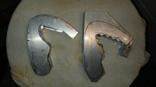
I drilled/tapped two holes in the sine table-top to mount a sacrificial "fixed jaw", made of hot-rolled steel. The vertical face of the jaw was milled flat, but not ground or scraped. I don't have a surface grinder and have no clue on how to scrape something only .125" wide. On the other hand, I'm aiming at making some tapered gibs so that is not a real issue anyway.
In the lower right portion of the photo is the "moveable jaw" of the vise portion. 1/8" thick, the horizontal portion is sacrificial hardware store aluminum and is bolted down to a .5" square piece of HRS. The side of the sine table was drilled/tapped to accept three 10-24 mounting bolts, and the HRS was clearance-drilled and counter-sunk to match. At that point, the HRS piece was bolted to the sine table and both were milled until mutually flat. I rotated the table up 90 degrees and drilled two more holes on each side of the moveable jaw's center screw, and reamed them for a press fit to two 3/16" x 1" dowel pins (shown projecting out of the sine table). I later reamed the HRS piece for a clearance fit for the dowels. They were meant to keep the moveable jaw from rotating as it is tightened against work. The 3 horizontal screws are used to clamp the work. Issues here, see below.
So another problem is lift of the moveable jaw due to over-tightening of the 3 screws (due to flex of the dowel pins). I tried to minimize this by making a jaw that is just-barely wide enough to accommodate the material I want to machine (so the dowel pins have maximum contact with the jaw), but they are just two 3/16" pins seated .5" into the sine table. Not super rigid. But this IS a trial run -- eventually I need to make a larger one so I can make some 5" long tapered gibs, and this one isn't long enough for that. But is IS long enough to try making tapered gibs for the Y axis of my mini mill.
A second, longer, version may have more pins to improve the rigidity of the moveable jaw (but see concerns below). I think I also will make the sine table taller (in the Y axis) so I can put some bolts in to prevent the moveable jaw from lifting up with regard to the table -- with careful adjustment, that should keep the moveable jaw from lifting. My current version is too small to accommodate them. Oh well....
A final issue is that, while the moveable jaw DOES slide onto the dowel pins there is about zero tolerance for misalignment. To move the jaw up to the work I have to wiggle it down, pushing one side down then the other. Pulling it back is even more problematic. I thought the sharp edges between the holes and exterior surfaces might be digging into the pins and relieved them with a conical grinder bit, but that didn't make any difference.
So the plan for now is to make the table wider and deeper, so I can make longer gibs. Steel would be better than aluminum, but I need to check what I've got in that category. The table hold downs and bottom rolls will be coincident. And I will include 2-3 top bolts to keep the moveable jaw from lifting up as it is tightened against the work. Hopefully I can stick with just two dowel pins -- I'm concerned that 4 pins (the most likely increment) will introduce difficult or impossible tolerance requirements when it comes to installing the moveable jaw.


")