Wiring advice needed

Suzuki4evr

Registered
Registered
Joined
Sep 29, 2017
Messages
2,251
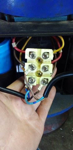
I want to use my old milling machine 2HP single phase motor to build a belt sander. Can someone please help by way of marking on the pics or diagram where to wire the Live and Neutral input wires. This motor have two caps so it use to run forward and reverse,but I only need to let it run one direction. Also if the wiring is sorted with your help,do O need to disconnect any of the other wires?
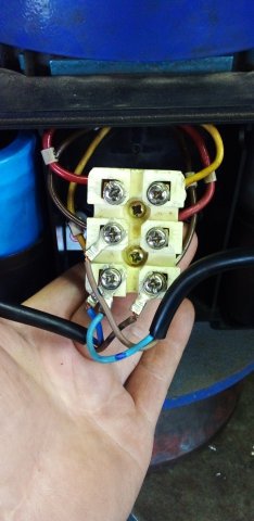
20211213_145630.jpg20211213_145630.jpg

Thanks in advance.
Michael
 
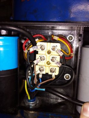
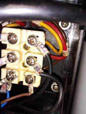
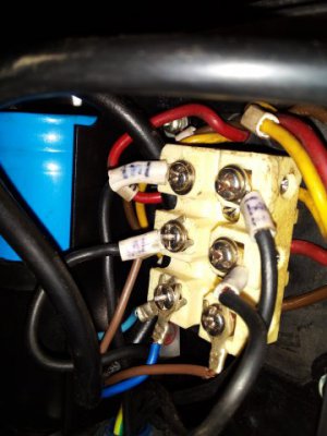
I am ading these for what it's worth. This is how it was wired when it was still in use on the mill.20210518_100906.jpg20210517_131004.jpg20210517_130935.jpg
 
The two caps may be to get the proper rating (paralled) or, more likely, one is a START and the other a RUN. In either case, there would be no call to remove one. Reversing is accomplished by reversing the relationship of two windings. The simplest approach is to set the motor in the desired direction and remove the handle from the switch. Then attach an ON/OFF switch in the line cord. For 120 volts, break the BLACK wire, for 240 volts break both. The GREEN is a ground and is never opened.

As far as rewiring, I am not familiar with your switching network so must abstain. The switch noted above should be motor rated, do not use a residential light switch except to test run.

.
 
The motor is basically a 3phase motor
It is using the capacitor to make the 3rd leg in both directions
You can put momentary power to the 1and 3 terminals and see which direction the motor spins
You can then see which capacitor is used for the desired rotation and you can remove the un-needed capacitor
 
remove the handle from the switch.
Bill what do you mean by this? There is currently no switch conected. Can you tell me where the postive and neutral 220V supply should be wired to? I also think you must totaly disregard the second set of pictures,because I only posted them to show how it was wired while the motor was still in use on the mill. The first set is how it is now and there is only red,brown, and yellow from the motor and the caps wires are blue and brown, there are no black wires in play. Sorry for the confusion.
 
The motor is basically a 3phase motor
It is using the capacitor to make the 3rd leg in both directions
You can put momentary power to the 1and 3 terminals and see which direction the motor spins
You can then see which capacitor is used for the desired rotation and you can remove the un-needed capacitor
Do I have it right if I then connect positive to the top left and neutral to bottom left? Is that what you mean by first and third?
 
Partially correct
The upper left and the 2nd terminal from top on the left
 
Sorry if I repeat stuff,but I don't want to blow something. So postive supply to red wire terminal from motor side and neutral to brown wire terminal from motor side? Do I leave the brown wire off the capp there?
 
I think you got it!
Leave both capacitors hooked up until you get the direction you want
 
just a fyi- discharge the capacitors before you handle the terminal block or the capacitor wires
 
Back
Top