Up front, let me apologize for making some invalid assumptions. I was in a hurry and didn't read the post thoroughly. Just skimmed. . .
Your motor is probably three phase with the third phase being generated by the capacitors. Swapping the caps from one line to the other should reverse the motor. That there are two caps could be one of several possibilities. The
most likely being in parallel with each other to increase the value. But that is an assumption, not a hard and fast rule.
I am not knowledgable of your power distribution system, the line feeding your building. I
think that you have a 240 volt feed on one lead and the second is at ground potential. I think. . . If that is indeed the case, the only line that needs to be switched is the line or "hot" lead, requiring a single pole switch. If, on the other hand, both lines are "above" ground, a two pole switch will be required, breaking both lines. This may be confirmed best by speaking to someone technical from the power company. In most cases, if you have a volt meter, it can be checked by reading voltage from both lines to a known good ground. Be aware that the ground must be a
good ground, a buried metal water pipe being a good source. With one line reading full line voltage and the other zero, you only need to switch one line. My only experience with such systems is from Australia and New Zealand and Micronesia. Many of the latter were setup to U.S. configuration, with two hot lines at 240 volts and 120 volts line to neutral. Some at 60 CPS, some at 50.
You stated the motor had been reversable when attached to a milling machine. My mind made the transition to the lathe as including the reversing switch. This is
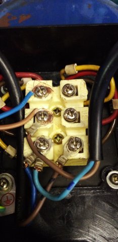
apparently not the case. It being reversable can be useful at times on a lathe but usually is not an absolute requirement. So there is probably no installation for a reversing switch. However, there will be an ON/OFF switch. Or should be. . . That switch is where a single pole or two pole makes a difference. In the U.S., an ON/OFF switch is often incorporated in a three position reversing switch. As in a FWD/OFF/REV switch. How that is wired is a factor of the type of switch as well as "user" preference, leading to a wide number of wiring configurations. There are several connections for power and reversing. Looking at your terminal block without knowing how it is wired internally is essentially meaningless to me.
There are electrical reasons for an ON/OFF switch, but the most important is a factor of
safety. There
MUST be some way to idle the machine quickly and easily. A brake is of concern on a larger machine, but only a convenience on a smaller. There are users (members of this board) that have multiple power switches located away from the machine. That is a factor of personal paranoia as well as the machining of flammable materials. In any case, the machine should be attended whenever it is running. I personally have only one switch that is located away from the machine so can be reached no matter which direction I run. But no matter what arrangment you decide on, unplugging the machine to stop it is not an acceptable method.
As a side note, your reference to "
positive and neutral" applies only to DC systems such as a battery powered system. The more valid reference for AC would be "line and neutral" or colloquially "hot and ground". There are many terms for both, some being technical, some colloquial, and some regional. In this case, the latter is most likely to be confusing.
Bi11 Hudson