- Joined
- Sep 29, 2017
- Messages
- 2,251
Hi Mark.I'll see if I can put together a quick sketch- stay tuned
-M
Question: the motor wires have those little white beads on them- do those have legible numbers?
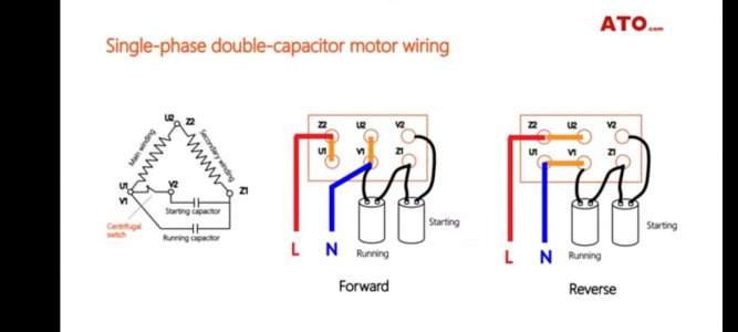
Here's a motor plate diagram which seems to match yours: The bottom two configurations represent clockwise and counter-clockwise for 220 volts
You strap across as shown and the power comes in the bottom
My brother inlaw came around,I spoke to you about him back when you were helping me with the wiring of my mill VFD, and he showed me this configurations and we wired it for running forward and it is running perfect. Now I don't know why there is different configurations for the same tipe of motor,but this one works. I am curious that if I am going to connect the wiring like the information plate you posted,if it will also work,but I'm not willing to take the chance though. Would it work,what do you think?
Michael