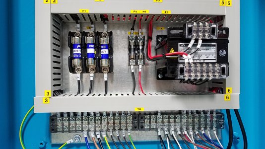
Wiring my 3 Phase Lathe to my RPC

This is a pertinent, basic video that I find helpful:

 
Yeah, it's not that complex. Three phase is just the three wires, switch any two to change direction, ground is ground. The 220V single phase is also simple, two hot legs, one neutral and one ground.

But, sorry to tell you you're going to have to send that plug back. It's an L15-20, similar but not the same as the L15-30 notice the tang points out instead of towards the center.

I'm still for hard-wiring the lathe though. In addition to saving the flexible cords for stuff that needs to move around you get the advantage of running your conductors in conduit which will protect them from cuts and burns.

John
 
That is ridiculous that they sent me the wrong male and female plugs. I did all of that in one order!
 
They are easy to get mixed up, hopefully they'll just send you the right one and you can use the other on a generator.

John
 
Yeah, it's not that complex. Three phase is just the three wires, switch any two to change direction, ground is ground. The 220V single phase is also simple, two hot legs, one neutral and one ground.

But, sorry to tell you you're going to have to send that plug back. It's an L15-20, similar but not the same as the L15-30 notice the tang points out instead of towards the center.

I'm still for hard-wiring the lathe though. In addition to saving the flexible cords for stuff that needs to move around you get the advantage of running your conductors in conduit which will protect them from cuts and burns.

John

That was a really good catch on your part to notice that the male and female plugs can’t connect together. I just called American Rotary, and they are going to send out the proper replacement and a return label for the wrong male plug. I don’t think that there is a charge for that.

I have had this RPC for over 3 months, just sitting here waiting for my new lathe.
 
Ask me how I know this ;)

John
 
As mentioned, the plug is a 30A 4 prong. According to the AMP RPC manual L1 and L2 are the line voltage and L3 is the manufactured leg. The ground is typically the dog legged prong on twist locks, it should also be marked green on the screw. You will need to check with American Rotary as to which prong on the plug in the AMP is the wild leg (I am assuming this is the Z). I would suggest that for L1 you use the black wire, L2 use the red wire and L3 (wild leg) you use the white wire. Typical convention is to wrap a different colored tape (around the white wire to denote it is not a neutral, I will often use some, black, red or brown tape) but doesn't matter in this case. At the lathe you will need to connect the wires to the terminals labeled R, S, and T. The lathe power transformer should have the wires labeled, in the last RL lathe I did an install on, the transformer terminals were labeled R and T (see below) so the wild leg should not be connect to R or T. If you motor is running the wrong direction, then flip the R and T wires at the power connection terminal strip. Be sure ALL POWER IS OFF. You can connect bare wire to the RST connection terminals but I prefer crimped with a locking spade. The crimps must be correctly sized and crimped properly, so if you have an electrician friend maybe have him/her look it over or give you a hand.
R = Black Wire L1
S = White wire L3
T = Red Wire L2

GREEN, GREEN/YELLOW is always ground connect to the "E" terminal.
20180209_120553.jpg
 
As mentioned, the plug is a 30A 4 prong. According to the AMP RPC manual L1 and L2 are the line voltage and L3 is the manufactured leg. The ground is typically the dog legged prong on twist locks, it should also be marked green on the screw. You will need to check with American Rotary as to which prong on the plug in the AMP is the wild leg (I am assuming this is the Z). I would suggest that for L1 you use the black wire, L2 use the red wire and L3 (wild leg) you use the white wire. Typical convention is to wrap a different colored tape (around the white wire to denote it is not a neutral, I will often use some, black, red or brown tape) but doesn't matter in this case. At the lathe you will need to connect the wires to the terminals labeled R, S, and T. The lathe power transformer should have the wires labeled, in the last RL lathe I did an install on, the transformer terminals were labeled R and T (see below) so the wild leg should not be connect to R or T. If you motor is running the wrong direction, then flip the R and T wires at the power connection terminal strip. Be sure ALL POWER IS OFF. You can connect bare wire to the RST connection terminals but I prefer crimped with a locking spade. The crimps must be correctly sized and crimped properly, so if you have an electrician friend maybe have him/her look it over or give you a hand.
R = Black Wire L1
S = White wire L3
T = Red Wire L2

GREEN, GREEN/YELLOW is always ground connect to the "E" terminal.
View attachment 340193

I very much appreciate your comprehensive and tremendously helpful response.
 
Last edited:
A good friend of mine weighed in via email. I have paraphrased most of his points here:

American Rotary will be able to tell me which female prong comes from the manufactured leg. The corresponding male prong should go to the motor in the lathe and NOT to any other circuits or transformers (with the understanding that it will pass through some motor switching). This is because the voltage & phasing of the wild lead is variable (and thus less stable than the other two hot leads).

The leads which are not wild are more desirable for servicing controls and electronics.

He is not sure of any risks associated with attaching the wild lead to controls, circuits and/or transformers, and he recommends that I check in with both American Rotary and Precision Matthews.

The voltage of the manufactured leg is generated by the motor and capacitors, etc. in the RPC.

I hope that I was accurate in paraphrasing him.
 
Last edited:
Back
Top