- Joined
- Mar 26, 2018
- Messages
- 2,725
Its been quite a while without an update here!
I spent a good two weeks trying to identify an issue which would cause my machine to move unexpectedly and violently every time I enabled the motors, tried to home the machine, or jogged in any way. After recording a ton of data and presenting it to Warp9TD, we were able to find that the was an anomaly in their code/interface with Mach 4. Andy was extremely helpful and they were able to correct the issue immediately in the next release of the plugin. Everything seems to be working great now!
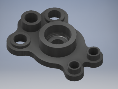
I wanted to try out the machine with the latest features I added. To do this, I drew up a slightly complicated part up in Inventor. Rough size is 4x2x1".
This was programmed in MasterCam. There were 9 tools used in 10 operations.
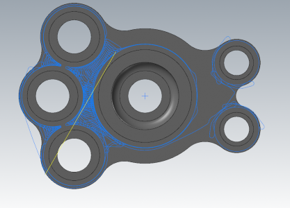
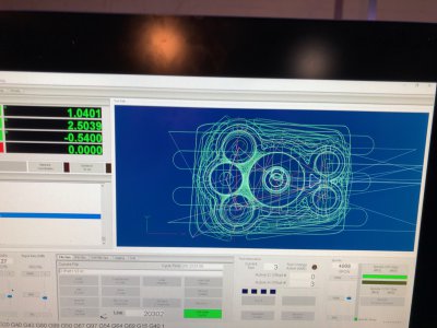
Here is OP6 rest machining shown in MasterCam.
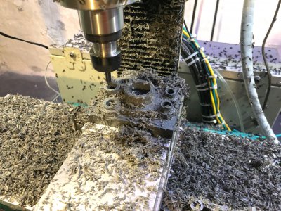
Here are a few pictures of the process. I also have a couple of short videos if anyone is interested. I can't seem to post anything longer than 18 seconds so it is rather limited. If you could tell me how I'd really appreciate it.
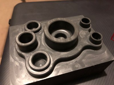
And the finished part right off the machine. Material was solid PVC. Tool marks are super visible because it is dark plastic, but the surfaces are very smooth. If I were to run this part again, I would tweak a few things to make it more efficient and to avoid a few blemishes where the dynamic roughing marks were never cleaned up by the finish passes.
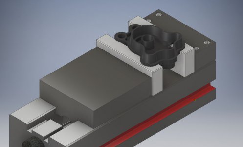
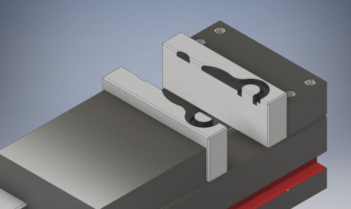
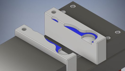
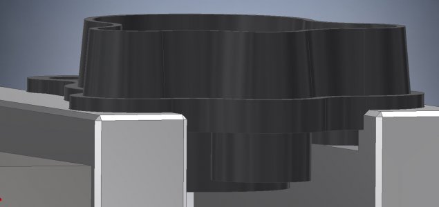
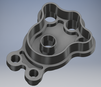
After having so much fun working on this part, I decided to really test myself and design a backside to the part. This will require machining of soft jaws (which I have never done before). The "fence" around the part is 0.5" tall with a 5 degree taper on the walls. The cavities in the part are setup to be machinable with the 5/32 cutter and are 0.2" deep into the 0.25" thick lower rim.
I already own a HSS 5 degree cutter so it should be good practice to program a tapered cut. The hardest part will be keeping everything aligned such that the through holes line up with the edge of the tapered web.
Will keep everyone updated with how this adventure goes.
I spent a good two weeks trying to identify an issue which would cause my machine to move unexpectedly and violently every time I enabled the motors, tried to home the machine, or jogged in any way. After recording a ton of data and presenting it to Warp9TD, we were able to find that the was an anomaly in their code/interface with Mach 4. Andy was extremely helpful and they were able to correct the issue immediately in the next release of the plugin. Everything seems to be working great now!
I wanted to try out the machine with the latest features I added. To do this, I drew up a slightly complicated part up in Inventor. Rough size is 4x2x1".

This was programmed in MasterCam. There were 9 tools used in 10 operations.
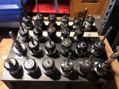
- 3/4" endmill used to face the part
- 3/8" ALU-Power endmill: Dynamic roughing and island facing
- #3 Spot drill to spot the 6 drilled holes
- 1/2" endmill to drill the 4 large holes. This was the first time I used the chip break canned cycle. It worked great!
- 3/8" endmill to drill the smaller holes. Also used a chip break canned cycle
- 5/32 endmill to clean up what the 3/8" endmill left behind. I used a dynamic rest machining operation which was very efficient. This tool also did a contour to finish the walls of the cylindrical bosses.
- 1/4" endmill to rest machine the lower profile (too deep for the 5/32) and finish.
- 3/8" ALU-Power endmill again to do a helical bore on the larger center bore.
- 1/4" ball endmill to finish the central boss inner wall and cut the 1/8" radius on the floor
- 1/4" Chamfer endmill to cut a 0.020" chamfer on all edges

Here is OP6 rest machining shown in MasterCam.

Here are a few pictures of the process. I also have a couple of short videos if anyone is interested. I can't seem to post anything longer than 18 seconds so it is rather limited. If you could tell me how I'd really appreciate it.


And the finished part right off the machine. Material was solid PVC. Tool marks are super visible because it is dark plastic, but the surfaces are very smooth. If I were to run this part again, I would tweak a few things to make it more efficient and to avoid a few blemishes where the dynamic roughing marks were never cleaned up by the finish passes.

After having so much fun working on this part, I decided to really test myself and design a backside to the part. This will require machining of soft jaws (which I have never done before). The "fence" around the part is 0.5" tall with a 5 degree taper on the walls. The cavities in the part are setup to be machinable with the 5/32 cutter and are 0.2" deep into the 0.25" thick lower rim.
I already own a HSS 5 degree cutter so it should be good practice to program a tapered cut. The hardest part will be keeping everything aligned such that the through holes line up with the edge of the tapered web.

Will keep everyone updated with how this adventure goes.

