No photos of the first POTD which was disassembling a Glacern vise on my Tormach 1100. The handle turned really hard; nut/screw were imbedded with chips. Isn’t it great when one project leads to another? My Tormach has a Saunders fixture plate which is covered with Saunders rubber chip deflectors. These have 4 studs on the bottom which plug into the plate and (hopefully) manage chips off the table and into the chip pan. I didn’t shoot photos of it, but with the vise off the table, the chip protectors were pulled also. Every fixture plate ½” hole was filled with chips. . . I pulled the fixture plate and the T-slots on the mill table were filled also. The Tormach’s table has a couple of drain holes about ½” diameter with a strainer above. These were filled with chips also.
I think what happened (besides my obvious poor job on preventive maintenance) was the Saunders rubber chip covers had distorted over time because of coolant (?) and warped. This let the coolant/chips get under the covers to the fixture plate and drain through the holes. The Tormach table strainers were overwhelmed with chips and coolant/chips filled the T-slots.
The Saunders rubber fixture plate covers have pins on the back side that press into the fixture plate holes. You can see in the upper LH photo how warped they set on my fixture plate (1 1/4" hole spacing). A quick caliper check across two of the pins shows the dimension is big by 0.1"; that explains the buckling between the inner and outer pins. Curiously, I don't see these rubber covers for sale on the Saunders website.

So, POTD was making better (hopefully) table covers to manage chips off the table. Material of choice was some 1/8” acrylic plastic on hand. Now, how to mount the sheets to the table. One thought was to simply drill some holes through the plastic and make up some ½”-13 bolts to screw the plastic directly to the table. Another thought was to make up some pins threaded ½”-13 (or use headless set screws) and hold the plastic down with magnets over the pins/screws (fixture plate is aluminum).
I went the laborious, over-kill route instead. . . I went with a sheet metal back edge “C” section that slips over the fixture plate and a spring-loaded pin/clamp at the front. The sheet metal was galvanized duct work stock on hand. Time will tell if it starts to rust at which point I’ll go with aluminum flashing.
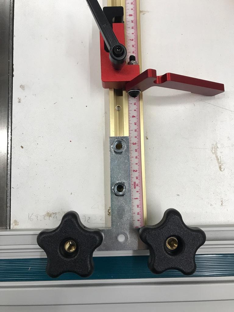
The front clamp was made from aluminum. Idea was to have a tapered pin that catches the bottom of the fixture plate. It’s easily removed from the table by pulling back on the pin, lift up the cover and slip it off the back.
The 1/8" acrylic was cut on the table saw with a zero-clearance blade insert. I used this insert as a normal one has too much clearance between the blade and insert, results in the plastic snagging/breaking on the edge (ask me how I know)

My prototype with just a sheet metal front edge (was way too flimsy). Sheet metal "C" section on the back slips over the fixture plate. The clamping pin rides in the mounting block and catches the bottom of the fixture plate.

Knobs were made from 1/2" aluminum. Knurled a long length, drill/tapped a center hole and started parting on the lathe. Ended up pulling the stock from the lathe and cut off on the band saw (way too much stick out from the chuck to comfortably part).

Clamp pins were made from 1/2" aluminum. Turned a shoulder to 3/16", ran a 10-24 die over for screwing to the knob, parted and cut a chamfer.

Mounting blocks (3/4" x 1" aluminum bar stock) were done on the Bridgeport. Drilled/tapped 8-32 mounting holes. Then drilled a 3/16" through hole for the clamp pin. Countersunk a clearance hole for the compression spring just short of the bottom with a 5/16" end mill and a second 1/2" hole for the head of the clamp pin.

Separated the mounting blocks on the DoAll saw with the power feed. Then milled the sawed ends. Being inherently lazy, did three of them at a time on the Bridgeport. Used 5/16" dowel pins in the spring clearance hole to set height; machinist's square to set them in the vise. Dust off the top on one side, flip, and milled the opposite side.

Mounting brackets were made from 1/8" thick aluminum stock. Drilled, countersunk on the BP.

Bent the brackets on the DiAcro brake. I didn't show it, but the brackets were set on the plastic cover which was already drilled for a sheet metal lip on the front. Used a transfer punch to mark the screw hole.

All of the components. Compression spring slips over the clamp pin, pin loaded into the mounting block, knob screws on the opposite end and the whole assembly screws to the plastic cover.

Side view under the fixture plate. The tapered pin catches under the plate. The cover can be pulled by pulling back on the knob, then lift and slip the cover off the fixture plate.

I made up 4 of the covers; two for outside of the vises and a pair of 6" wide ones to cover the plate if the vise(s) are pulled.

Next POTD will be coming up with some covers for the screws/nuts on the Glacern vises.
Thanks for looking, Bruce