

-
Welcome back Guest! Did you know you can mentor other members here at H-M? If not, please check out our Relaunch of Hobby Machinist Mentoring Program!
- Forums
- THE PROJECTS AREA
- PROJECT OF THE DAY --- WHAT DID YOU DO IN YOUR SHOP TODAY?
- Project of the Day Mega-Thread Archives
You are using an out of date browser. It may not display this or other websites correctly.
You should upgrade or use an alternative browser.
You should upgrade or use an alternative browser.
2020 POTD Thread Archive
- Thread starter eugene13
- Start date
- Joined
- Oct 16, 2019
- Messages
- 6,596
Ha! Figure 8 motion on medium sand paper on a flat surface!
Robert
@rwm + flat surface = surface grinder

Sent from my iPhone using Tapatalk
- Joined
- Dec 21, 2018
- Messages
- 1,829
How did you index the holes? DRO bolt circle function?I finally finished my 127-hole index plate. Yeah, it took me a while - breaking your only #32 drill bit in mid flight is frustrating. But, once I had new ones, I could finish drilling the holes. Sheesh, 127 holes can wear out an arm.
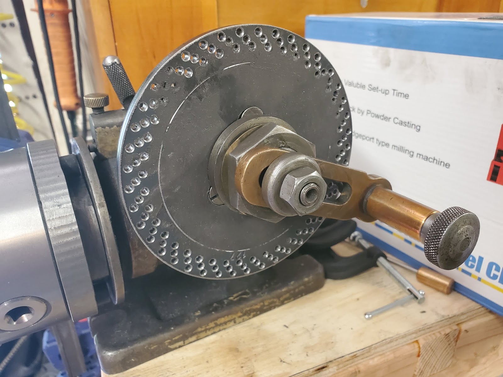
127 holes is not divisible by 3, and you can see the 126 holes (42 sets of 3) with the single remaining hole to the upper right corner. Now I can make big, ugly, 16 pitch metric conversion gears if I can get the indexing head far enough off of the table.
- Joined
- Dec 6, 2015
- Messages
- 813
No. I printed a circle with 127 divisions. Considering that there wasn't enough space on a single row, I had to offset into three rows. Even if I got the holes drilled 0.040" off, the accuracy will still be +/- 0.001" because of the ratio on the dividing head. If I chose, I could still drill another one using the plate and have it be 40 times more accurate than this one (it's a bootstrapping process), and repeat as necessary. But for terms of gear cutting, this one is accurate enough.How did you index the holes? DRO bolt circle function?
joe


- Joined
- Sep 28, 2013
- Messages
- 4,319
a friend of mine is doing a restomod on a '57 Ford F100 (I think) and needed a new shifter as the one that came on the '89 Mustang GT 5.0 he stuffed in there (old V8 needed too much work to be economical to fix) only came up to his ankle.
So I made a new shifter rod and bracket out of a piece of 5/8" stainless rod (scrapyard find) and some alu scrap

and then started hacking away at a piece of 4.5 x 2 x 1.75" piece of alu. Drilled it ~3.5" deep for a 3/8-24" thread (what I thought was the female thread on the end of the shifter rod), then realised that I had no way of tapping a hole that deep. Doh! So made this with spit and superglue

in action

then bored and reamed the hole 2.5" deep to 5/8" to match the shifter rod

also made a 3/8-24 set screw to join the female threads on the shifter with the female threads on the shifter rod. Only later found out it was some weird azz fine M10 thread. Doh!
so, got the shifter rod's sister, cut the end off and retapped it 3/8-24. Added a set screw and we're now set up for shaping the shifter

stuck it in a collet block then tilted and skewed it to the right angle

close up

used a 1/2" round over router bit for the ends and corners, then a ball end mill for the finger cut outs, then a hell of a lot of work with some files to finish shaping the profile

My friend politely told me that stamped numbers was not really the look he was going for, so a good friend stepped up and made me a couple of shifter medallions with the same shift pattern and numbers as the original Mustang shifter. A very big thank you! I owe you one

Boring out the recess for the medallion. Screwed up the first time (they were 33.xx mm in diameter, not the 35.xx mm my eyes somehow read on the caliper) so cut the shifter back 3mm and started again.

Ended up with a pretty tight slip fit. Tight enough that I had to use a suction cut to get it out after test fitting! A bit of JB weld and 24h later:

Next step was anodising. What a pain the proverbial that turned out to be. Took 4 tries before I got something that wasn't purple (not his style) and then it was a another whole pain in the.. to do the numbers. I tried blanking the shift pattern with superglue after anodising, but cleaning up the edges with acetone screwed up the oxide layer so the top looked like a$$ after dying. I then painted the pattern black, but machining the surface down pulled some of the paint out. ARGH! A little touch up and a coat of lacquer and we have...


fitting it to the truck this afternoon. A fun project but I'll be glad to see the back of it - it's taken a LONG time and I want to do something else for a change
So I made a new shifter rod and bracket out of a piece of 5/8" stainless rod (scrapyard find) and some alu scrap
and then started hacking away at a piece of 4.5 x 2 x 1.75" piece of alu. Drilled it ~3.5" deep for a 3/8-24" thread (what I thought was the female thread on the end of the shifter rod), then realised that I had no way of tapping a hole that deep. Doh! So made this with spit and superglue
in action
then bored and reamed the hole 2.5" deep to 5/8" to match the shifter rod
also made a 3/8-24 set screw to join the female threads on the shifter with the female threads on the shifter rod. Only later found out it was some weird azz fine M10 thread. Doh!
so, got the shifter rod's sister, cut the end off and retapped it 3/8-24. Added a set screw and we're now set up for shaping the shifter
stuck it in a collet block then tilted and skewed it to the right angle
close up
used a 1/2" round over router bit for the ends and corners, then a ball end mill for the finger cut outs, then a hell of a lot of work with some files to finish shaping the profile
My friend politely told me that stamped numbers was not really the look he was going for, so a good friend stepped up and made me a couple of shifter medallions with the same shift pattern and numbers as the original Mustang shifter. A very big thank you! I owe you one
Boring out the recess for the medallion. Screwed up the first time (they were 33.xx mm in diameter, not the 35.xx mm my eyes somehow read on the caliper) so cut the shifter back 3mm and started again.
Ended up with a pretty tight slip fit. Tight enough that I had to use a suction cut to get it out after test fitting! A bit of JB weld and 24h later:
Next step was anodising. What a pain the proverbial that turned out to be. Took 4 tries before I got something that wasn't purple (not his style) and then it was a another whole pain in the.. to do the numbers. I tried blanking the shift pattern with superglue after anodising, but cleaning up the edges with acetone screwed up the oxide layer so the top looked like a$$ after dying. I then painted the pattern black, but machining the surface down pulled some of the paint out. ARGH! A little touch up and a coat of lacquer and we have...
fitting it to the truck this afternoon. A fun project but I'll be glad to see the back of it - it's taken a LONG time and I want to do something else for a change
- Joined
- Oct 16, 2019
- Messages
- 6,596
Wow @mattthemuppet2, that was a ton-o-work! Brilliant end result.
Last edited:
- Joined
- Oct 16, 2019
- Messages
- 6,596
Noted & correctedWasn’t me @DavidR8