Aluminum Meat Mallet

The wife and other ladies actually prefer the shorter taper and longer grip on the handle.
Hm..........................................TMI ! :grin:

Looking good though ! :encourage: I found a crab mallet the other day I made back in jr. high school way back when . Crude to say the least , but I guess it would still crack a crab . ( if I could afford them these days )
 
I've cut 90 degree V-grooves on my benchtop mill using a carbide-tipped router bit and had problems when the groove depth went up. The faces being cut were wide enough to make the mill work fairly hard, and it didn't like it.....unless I used very small DOC's, which took forever. Sounds familiar, huh.

I switched to doing step-milling with different-sized flat-bottom end mills and only used the V-shaped router bit near the end to finish up the grooves. That sped things up a lot, but complicated the setup because I had to determine how deep I could go with the end mills. Simple trig does it.

One of the problems with the V shaped router bit (and countersink bits) is the straight cutting edge, so both sides of the groove are cut at once. As the length of the faces increases, the cutting load increaes as well. Starting with a bigger DOC, then decreasing it as you progress, also would speed things up (some). A spiral-cut countersink could make a difference but they don't appear to exist. Probably not easy to make.

I think the cutting forces would be greatly reduced if one could tilt the work or column then advance a standard flat-bottomed end mill in a way that uses the spiral-cut sides of the EM. Hard to visualize how it could easily be done with the column tilted but fairly straightforward if the work is tilted.

If you have a slitting saw you also could use that. You'd have to rotate the piece 180 degrees to complete the Vees. That alone favors the use of an end mill, but it has the advantage of not having to turn the entire volume of the Vee into swarf.
 
I have attached a spreadsheet (WARNING: untested) that should calculate the steps needed to rough-cut a Vee profile using a standard flat-bottomed end mill. It allows for different sizes of end mills, included angle, end mil DOC and the DOC for the final finishing pass. It also approximates the number of passes needed per depth increment. The latter information will be helpful if using an end mill that is substantially smaller than the starting width of the Vee, to help the user determine if they want to go to the trouble of doing it that way or not!

If users want a specific depth they will have to back-calculate what the top width of the Vee needs to be.
 

Attachments

  • Vee profiles rough cutting.xls
    11.5 KB · Views: 5
Thank you for taking the time to do this. It is starting to appear there is no way to make the cuts to depth fast. It takes time. I also have a side-cutting 60° chamfering tool that I will try. Heading towards a learning curve. Danger ahead. Thanks again. Terry - W6LMJ
 
I've cut 90 degree V-grooves on my benchtop mill using a carbide-tipped router bit and had problems when the groove depth went up. The faces being cut were wide enough to make the mill work fairly hard, and it didn't like it.....unless I used very small DOC's, which took forever. Sounds familiar, huh.

I switched to doing step-milling with different-sized flat-bottom end mills and only used the V-shaped router bit near the end to finish up the grooves. That sped things up a lot, but complicated the setup because I had to determine how deep I could go with the end mills. Simple trig does it.

One of the problems with the V shaped router bit (and countersink bits) is the straight cutting edge, so both sides of the groove are cut at once. As the length of the faces increases, the cutting load increaes as well. Starting with a bigger DOC, then decreasing it as you progress, also would speed things up (some). A spiral-cut countersink could make a difference but they don't appear to exist. Probably not easy to make.

I think the cutting forces would be greatly reduced if one could tilt the work or column then advance a standard flat-bottomed end mill in a way that uses the spiral-cut sides of the EM. Hard to visualize how it could easily be done with the column tilted but fairly straightforward if the work is tilted.

If you have a slitting saw you also could use that. You'd have to rotate the piece 180 degrees to complete the Vees. That alone favors the use of an end mill, but it has the advantage of not having to turn the entire volume of the Vee into swarf.
I have a 60° slitting saw/chamfering bit, which I plan to try. Thank you for your very helpful comments. Terry - W6LMJ
 
I have attached a spreadsheet (WARNING: untested) that should calculate the steps needed to rough-cut a Vee profile using a standard flat-bottomed end mill. It allows for different sizes of end mills, included angle, end mil DOC and the DOC for the final finishing pass. It also approximates the number of passes needed per depth increment. The latter information will be helpful if using an end mill that is substantially smaller than the starting width of the Vee, to help the user determine if they want to go to the trouble of doing it that way or not!

If users want a specific depth they will have to back-calculate what the top width of the Vee needs to be.
If there's enough interest (TBD) it wouldn't be too difficult to add another variable parameter, the amount of overlap between passes, to more-accurately predict the number of passes per Z step. Not so sure about the actual step-over coordinates because the number per Z step will vary, depending on Z.
 
If there's enough interest (TBD) it wouldn't be too difficult to add another variable parameter, the amount of overlap between passes, to more-accurately predict the number of passes per Z step. Not so sure about the actual step-over coordinates because the number per Z step will vary, depending on Z.
Overlap? To duplicate the head of the meat mallet, I set the distance between cuts to the width of the original mallet head. I took a very direct approach. Having determined the chamfer needed to be 60° I bought the chamfering tool, mounted it in the collet, and used the DRO to measure the distance by literally placing the bit in the existing cut and noting the distance between cuts, The image below is an early setup, before clamping in the vise, to learn how to do it. I might add, that the bit in the image is carbide and I broke it trying to be too aggressive making early cuts. I switched to a cheap HSS bit and have more than six hours of cutting aluminum with it. It seems to be holding up well. But I have slowed the mill down to about 700 RPM and have been making much shallower cuts with a slow feed rate. I have a power feed on the mill but have not discovered how to measure the feed rate, other than trial and error. Terry - W6LMJ
 

Attachments

  • Setting cut distance.jpeg
    Setting cut distance.jpeg
    432.2 KB · Views: 9
As many may recall my project is to recreate a meat mallet that I made in high school. This was to be a re-learning project to reacquaint me with machining and operating a home machine shop.

I bought a 7X14 mini-lathe and successfully made a couple of handles. Working with a 3/4" aluminum rod gave me a chance to become familiar with the lathe as I turned, threaded, tapered, and knurled the mallet handles.

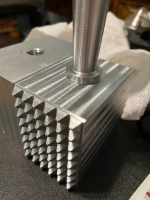
I bought a PM-728VT mill, and then I made a meat hammerhead and that turned out well. With Christmas four months away I decided the next step would be to produce about seven more meat mallets. The first took about 30 hours of learning with about 20 hours of machining. I am hoping to reduce the time invested to about five hours of machining, each. Along the way, I ordered a TM-1236 lathe which should make short work of the meat mallet handles.

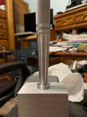
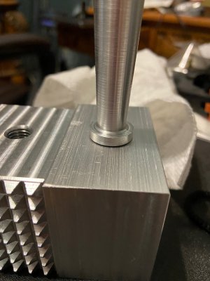
I added the table power feed and plan to add a power feed to the column to make changing bits easier. I have however run into a problem. Drilling and tapping the mallet head seemed perfect for the first one. Centered and perpendicular to the head. The handle looked like it was machined after screwing it into the mallet head (-:). However, I have not been able to duplicate that precision during the subsequent production. None of the subsequent drilled and taped holes are precise. The handles tilt. I feel I could have done better with a hand drill.
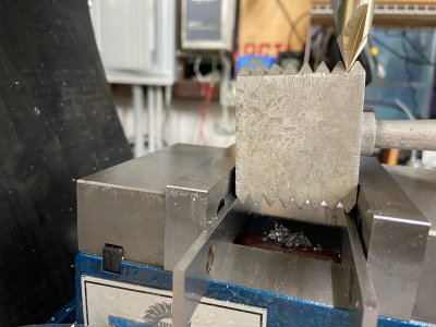
I used the center indicator to check the alignment of the mill, ensuring the vise is square and the column moves precisely vertically as it is raised and lowered, ensuring it is square to the table. I used a square mounted in the vise to give me about four inches of vertical to measure. I am about 0.002 over four inches on all axis. The error continues to be a puzzle. The first head came out perfect. However, all the rest (seven in all plus about four tests and tapped holes) did not.
One mistake I may have made is drilling centering holes. I did seven mallet head blanks one after the other. This means after drilling the centering hole, I unclamped the piece and drilled the next. I worry that the centering holes actually serve to guide the tape drill to one side or another disturbing the precision. But I did a few tests where I drilled the centering hole, and replaced the centering bit with the tap drill, but ended with a similar error.

Again all suggestions are greatly appreciated.
 

Attachments

  • Not perfectly square.jpeg
    Not perfectly square.jpeg
    225.3 KB · Views: 7
  • Showing the gap.jpeg
    Showing the gap.jpeg
    224.3 KB · Views: 6
  • Handle flush to head.jpeg
    Handle flush to head.jpeg
    277.7 KB · Views: 7
  • Centering Indicator.jpeg
    Centering Indicator.jpeg
    429.4 KB · Views: 6
Last edited:
Heic files are Apple specific, can you please change the file type? Can't view the pictures.
 
Back
Top