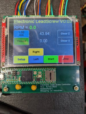
An Electronic Lead Screw controller using a Teensy 4.1

So you have a DRO scale, but not a DRO controller, or do you pass on the DRO pulses from your MCU to the DRO controller? If the former, I'm not sure I am interested. If the latter, then I am *VERY* interested.

My notion for the shoulder stop is pretty simple. In James' code, the <Set> key is unused at this point. That would make it a good candidate, assuming the use is employing the same simple control panel. This does not, of course, have to be the case.

In my vision, the <Set> key pressed once simply stops the lead screw if it is spinning and starts it if it is not, no matter what the controller mode. Pressing the <Set> key three times in less than, say, 3 seconds records the current lead screw position and starts the Shoulder Stop mode. In this mode, every second momentary press of the <Set> button reverses the lead screw direction, as does a press of the <Set> button after the controller has automatically stopped the lead screw.
I have just the read head directly connected to my PCB. No DRO controller needed. A DRO head is a linear quadrature encoder, my Teensy software counts all the edges and applies the cal factor to get position. Pretty simple. It knows fwd and rev. All interrupt driven
 
I hear you. It was worth a shot! On a related note, however, clearly you are familiar with the pinout and protocols of DRO scales, at least the ones you are using. Are you using optical scales, or magnetic? If the latter, do you know whether the two are the same? Can you point me toward some documentation?
My cheap DRO scales are magnetic. To determine the wiring I used a volt meter on the connector while it was plugged into the 1980s display that came with my lathe. I used the power supply ground as reference. A and B, well, I guessed. The scale is powered by +5V, the output levels are classic TTL. This is why I used a level translator on my PCB. Teensy 4.1 is not 5V tolerant. 5V will damage the device. Teensy 4.1 has 3.3V I/O.

For a bit more detail on scales I visited the diy dro site. You can find a link in the sponsor's forum.
 
Both DRO's are running now. Both are roughly calibrated. Took me two tries on both cables to get it right. Dunno, those numbers on the connector are hard to see! Once the cables were pinned correctly, the DRO's were functional. Surprisingly, I got the A & B signals correct, had a 50/50 chance of getting it right. Going towards the chuck increases Z. Going towards the spindle axis increase X.

Got to figure out how to stick on a 123 block and measure the travel. The sw encoder tool that I am using is pretty amazing, all the bounce stuff is taken care of. It just counts, and the counts are converted (by my code) to the proper units. Wish the encoder and tape were higher resolution though, I am limited to 0.001" resolution apparently. Would have been nice if they were 0.0005". Might look into some better scales.

Now I have to put in some zeroing functions for the DROs. Think that should be straight forward.
Once that is done, I have to review LH threading again. Think I have something not quite right there.
After that, is feeding to a stop.
Then threading to a stop. Hopefully I will figure some of thread to a stop while doing the feeding to a stop.
 
Added in some zeroing buttons for the DRO axes. Also the scale displays in mm, if metric feeding or threading is selected. That's not the most flexible thing to do. I may have to add yet some more buttons, to be able to have a choice between metric or imperial independently on the axes, but I am running out of real estate in the main menu. I don't care for toggle buttons, but may have to implement them to simplify the display.

Also added left and right handed threading buttons. I have not modified the state machine to do something with the button presses yet, but, I'm getting there. The UI desperately needs spiffing up. But that will have to wait until the essentials are in place.
PXL_20220930_212140691.jpg
Kind of cool gratifying to see the Z axis incrementing when the half nuts are engaged. At least at 888 RPM spindle speed, the stepper has no issues and the DRO is reading smoothly at the same time.
 
Last edited:
My second lot of boards came in (actually the first one's I ordered) from PCBWay today. Packaging was poorer than the first lot (JLCPCB). These are the one's that I had done lead-free. They were a lot more expensive than the JLCPCB one's, like 3X the price, comparing both at like features.

Also my GX style connectors for my box to box connections were delivered. Guess I will have no more excuses for the mess, and will have to build up the chassis. Back to the hard part, figuring out how to make it all fit!
 
This is all in relation to a 'wish list' item for my lathe. (Which I will hopefully be building this winter). The OP is basically on the same path I am on (albeit a long way ahead of me!).
I don't see a need for two set points. When threading or turning to a shoulder, only the stop point is critical. The button can be pressed manually after one resets the carriage position.
The goal would be DRO scale driven (corrected) threading. If you have a worn screw, the DRO can ensure the thread pitch remains constant. A side benefit is that syncing the screw to the DRO and spindle, it easily allows syncing up the thread no matter the pitch.

When manual threading there is a defined start point, where the operator synchronizes everything BEFORE entering the cut. We just never think about it that way.

Syncing a thread to a DRO scale AND the spindle would require a known start point to be sure the screw/DRO and spindle are in sync before proceeding. In code that start point would be the start of thread, and should also be the spindle index or zero degree position. That point can be used to calculate Spindle/DRO/Screw target positions.

I disagree. The ELS should not care when or whether the DRO starts or stops, presumably because the spindle has stopped rotating. Indeed, except for stopping the spindle to take measurements, the spindle should never stop turning.
Again, this is for a pretty specific process. With the process outlined above, if the operator disengages the half nut and the DRO stops moving, the code will have to assume the threading pass is done. The safest way to reengage to start the process again is to continue on (as though the STOP event happened). Again, this is a bit more functionality than a 'dumb' ELS provides.

That is true, but considerably more complex to implement.
Yes, a bit more complex. However I'll disagree with 'considerably'. If you're implementing threading to a stop, it isn't that much more to ensure you start at the same point every time.
 
At this point, I have no motivation to plow though the Clough42 code base, nor to port my code to the TI device, which has different hardware. That's a job for SW people at the top of their game. I'm just a guy that plodded along and exploited the capabilities of the Teensy 4.1 platform. I started coding on May 1st, having never used the device.
I have the Clough42 code up. It's not difficult to read, but the IDE (Eclipse) is new to me. He is a programmer by trade, so he obfuscates some things from us mere mortals without even knowing it! lol.

The arduino stuff is much easier to learn. Lack of a proper IDE is somewhat painful, but honestly with the Microchip PIC24 IDE I haven't used a single breakpoint in a decade. A USB to serial cable and one I/O pin, paired with a few I/O pins and a scope is much more useful. One of my next steps will be to add that USB/Serial cable to the Teensy to get some debug information out, although the built in USB/Serial is pretty useful as is.
Have my second board and display running. Simply partially populated it, and turned it on. Easy, peasy. I'm going to use it for UI work. It's kind of a pain to be down in the shop for that sort of thing, especially if you are learning new graphics tools.

Using the Teensy libraries made my life soooo much easier. The DRO's were almost trivial, a gimme. I'm even considering upgrading my read heads so I can put in a 5um system. My current DRO heads seem to be quite old, only capable of 0.001". Found the read heads for about $54 each, and 1m of 5um tape for ~ $40-50.

The Clough42 code isn't bad, but James didn't document his source code that well. I usually put in a lot more. I know from experience that if you do something elegant, or tricky, 3 months from now, you won't have an inkling of WTF you did, especially if life happened along the way. Trust me, you can't document your code enough!

I got around ICE with good old fashioned twiddling I/O pins and a scope. Good enough to establish timing and other stuff. The Teensy outputs on the serial port at USB2 speeds, or 480Mbit/sec, which is darn good for "serial". You can get a heck of a lot of data out that port, should you need it.

The Arduino IDE V2 has been released and it has Teensy support built in. I haven't tried it yet, but it looks to be a big step forward. It's looking much more like an IDE, as compared to V1.8.19 that I am running on.

I have absolutely no regrets for taking the path that I did. This project is turning out to be far, far better than I expected. It is so much easier to develop on Teensy than on any TI platform that I have tried over the past 15 years.
 
It’s looking great and it’s fun to watch your progress. Thank you.
 
Got to figure out how to stick on a 123 block and measure the travel. The sw encoder tool that I am using is pretty amazing, all the bounce stuff is taken care of. It just counts, and the counts are converted (by my code) to the proper units. Wish the encoder and tape were higher resolution though, I am limited to 0.001" resolution apparently. Would have been nice if they were 0.0005". Might look into some better scales.
That's a little strange. Most scales out there are either 5um (0.0002') or 1um(0.00004") resolution. It's hard to imagine a scale with only 0.001" resolution. Optical scales 900mm long and 5um resolution can be had under $50, and 1um scales the same length run a little over $100.
 
Back
Top