-
Welcome back Guest! Did you know you can mentor other members here at H-M? If not, please check out our Relaunch of Hobby Machinist Mentoring Program!
You are using an out of date browser. It may not display this or other websites correctly.
You should upgrade or use an alternative browser.
You should upgrade or use an alternative browser.
Atlas Horizontal mill
- Thread starter 34_40
- Start date
Regarding the M1-61 bar that provided additional support to the front of the overarm arbor support....
I passed an Ebay offering at 199.99 as too pricey, then I gagged when I saw another go a month later for $275. Seems these are rare birds. I am looking at prices for raw materials. Anything other than CRS bar stock is rather pricey. Local vendors of CRS Bar stock require I buy a minimum 20ft length. Cast iron flat, closest I found at speedymetals that will finish to final drawing size (15/16 x 2-1/4 x 15-1/2) is 2 x 2-1/2. An 18" length is $51.77. (I may do that.) At least it will be factory-type material. Tool steels of any alloy from any source are at least twice that or more and may prove difficult or costly in tooling to machine.
What do you folks think about using aluminum flat bar? 18" of 1 x 2-15 (6061-T5611) at Speedymetals is $21.31 plus shipping. Too soft and stretchey?
Spiral_Chips
- Joined
- Mar 24, 2016
- Messages
- 100
Spiral-Chips,
I may be preaching to the choir here, but my favorite strategy for finding pieces like the one you mention is to go to the local metal supplier and ask about drops... you never know until you ask, do you? I also had developed a loose relationship with a local scrap yard, unfortunately they have moved and I'll have to start over. Just because a piece of metal has been used before doesn't mean you can't repurpose it. I tend to be very frugal on such things and buy new metal (especially in expensive, large pieces) strictly as a last resort. After all, after you mill and drill and grind away all evidence of its previous usage, who cares?
Regards,
Froggie
PS I just started in again with rehabbing my MFC and that's one of the things I need... gotta get the overarm fixed up first, though.
I may be preaching to the choir here, but my favorite strategy for finding pieces like the one you mention is to go to the local metal supplier and ask about drops... you never know until you ask, do you? I also had developed a loose relationship with a local scrap yard, unfortunately they have moved and I'll have to start over.
Regards,
Froggie
PS I just started in again with rehabbing my MFC and that's one of the things I need... gotta get the overarm fixed up first, though.
Around here drops seem to get squirreled off pretty fast.
One possibility is I have two large pieces from a broken square storm drain frame made from cast iron. I may be able to saw a suitable piece from that.
Spiral_Chips
One possibility is I have two large pieces from a broken square storm drain frame made from cast iron. I may be able to saw a suitable piece from that.
Spiral_Chips
- Joined
- Mar 24, 2016
- Messages
- 100
While we're on the subject of the overarm, my Atlas MFC came to me with two empty holes where the arbor support arm locks are supposed to be... I have the arm itself, but no way to secure it from sliding and/or turning. I'm wondering what those parts (inside) even look like, and whether I can fabricate them myself or whether they are too complex?? The square head bolt and some sort of substitute for the (visible) locking levers should be pretty straightforward, but what about the sleeve parts that actually lock the arm?
Froggie
Froggie
- Joined
- Mar 3, 2013
- Messages
- 1,448
While we're on the subject of the overarm, my Atlas MFC came to me with two empty holes where the arbor support arm locks are supposed to be... I have the arm itself, but no way to secure it from sliding and/or turning. I'm wondering what those parts (inside) even look like, and whether I can fabricate them myself or whether they are too complex?? The square head bolt and some sort of substitute for the (visible) locking levers should be pretty straightforward, but what about the sleeve parts that actually lock the arm?
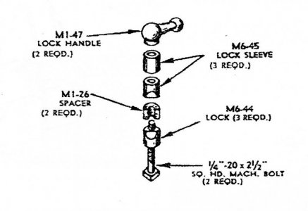
Here is the parts diagram. I think most parts would be easy to make except maybe M6-44 which has a recessed square hole in the bottom. Note that M6-44 and M6-45 were originally cast parts probably Zamac. If you need photos of the actual parts I can get them for you.

Those are not unlike the TS ram lock on the Atlas lathes. Not the exact same parts to be sure, but similar, made from ZAMAK. I would expect you could get satisfactory performance making them from 6061 aluminum. Just don't tighten any more than necessary to stop the support from moving.
The square recess in the bottom piece, M6-44, can probably be accomplished by boring a flat bottom depression with a diameter to match the width across the flats of the bolt head then using a very small diameter end mill to square it up.
Spiral_Chips
The square recess in the bottom piece, M6-44, can probably be accomplished by boring a flat bottom depression with a diameter to match the width across the flats of the bolt head then using a very small diameter end mill to square it up.
Spiral_Chips
- Joined
- Mar 24, 2016
- Messages
- 100
Thanks, Rich. That picture in my copy of the parts list is smaller (of course) and a little blurry. I'm still trying to figure out why I need three each of the M6-44 and M6-45 bushings. I see two '-45s and one '-44 being used on this one assembly, times two would be a total of six pieces according to the picture. If I do have to make a set of them, I'm thinking that some aluminum rod in my chowder box would be a good substitute for ZAMAC, don't you think? Also, I'm thinking the MI-26 spacer looks like it ought to be made of rubber, right? I'm thinking I can make a pretty usable lock handle without being too concerned about slavishly copying the original. The only other major external part I'll need to replace is the eccentric lever whose lever and knob are broken off on mine... there's a long machine screw in it to pull the locking pin, so at least I can use it as-is while I fix more pressing needs.
- Joined
- Mar 24, 2016
- Messages
- 100
OK, I guess I'm going to need detail drawings or pictures... the more I look and scratch my head, the more confused I get!  Is there a drawing I can access online, or where do I need to go to get one? From what S_C said, I'm guessing there is a notch across the bottom of M6-44 that engages the square head of the 1/4 x 20 machine bolt while M6-45 is the same but without the notch, right? Why are they showing the upper spacer as being a M6-44 when it wouldn't need the relief in the side to bear against the overarm bar? Again, am I right that the MI-26 spacer should be made out of rubber so it crushes when the assembly tightens against the bar? I'm still trying to figure out why the heck somebody would take both of these out entirely in the first place!
  Oh well, it's all part of the adventure, and since I'm retired now I have lots of time to enjoy working on it, right?
Froggie

Froggie
- Joined
- May 17, 2012
- Messages
- 104
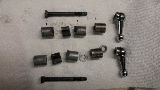
I'm working on rehabbing mine (see earlier in this note), so I took the locks out and took a picture. They are Zamak. Notice that mine were not the same. I think someone put the washers in after the lock started to wear. I also found out that one of the lock handles is stripped. Helicoil time I guess.
Mine are kind of beat up. The measurements that I get vary among the parts.
1 Dia=.615-.621, L=.709, Hole is a snug fit on an F drill(.257), the un-arced part is 1/2", the un-machined part of the nose at the narrowest part is 3/8", the square hole is 25/64.
2. Rubber, so dimensions are difficult but it's about 5/8" dia, 1/2" long, and the hole fits a J drill(.277) It appears to be cut off tangent to the center hole.
3. All similar to #1 but no square hole, length is .711
4. Dia=.6235, L=.6565, hold fits an I drill(.272).
When I put 1 and 3 on the bolt and make the arcs rest easily on the overarm, there is 5/8" between the ends of the parts.
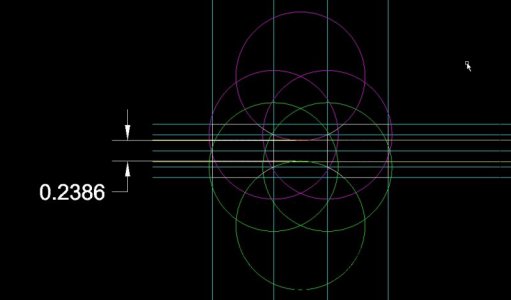
There are some problems with these dimensions. When I build a cad model, the arc that defines the two curved surfaces on 1 and 3 drops too deeply into the slot in between.
In the drawing, the blue lines are the centerline and outside of the parts, the yellow lines are the hole through the center of 1 and 3, and the green and magenta lines are used to construct the arcs. They suggest that the overarm will intersect the clamp bolt.
The rubber piece is 1/2" long, so I'm going to try a construction with that spacing. That will move the overarm away from the clamp bolt.


