Atlas Horizontal mill

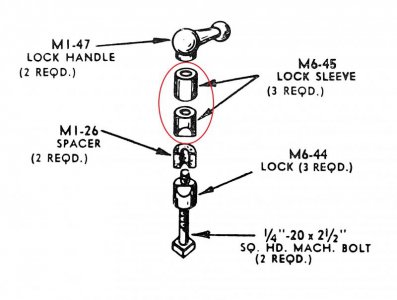
Why are they showing the upper spacer as being a M6-44 when it wouldn't need the relief in the side to bear against the overarm bar?

On my current model MFC the upper spacer (#4 in Wheels17 pictures) is a straight spacer with no relief but on the older model MF that I once had the spacer was just another M6-45 with the relief (which served no purpose that I can tell, probably just one less part number to deal with).
 
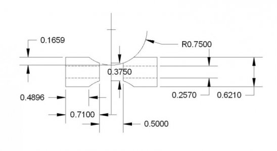
I redid the drawing with a half inch gap. It looks better, as there is now a gap of .2892 between the two arcs, so there's about .015 clearance from the overarm. Please excuse the ridiculous numbers of decimals. I need to carry them to make the fractions come out right. I need to make one of these once I get my arbor support made. I have not shown the square recess.

To make it, I think what I will do is make a part that is as long as the two of them, plus the half inch space in the middle. I have a 1.5" diameter horizontal milling cutter, so I'll put that on an arbor in my vertical mill and pass down both sides to the right depth. Then I'll cut 1/2" out of the middle.

Now what to use to make it? Wikipedia says Zamak 3 is "the defacto standard" for Zamak alloys, and has a yield strength of 30,200 psi. The other Zamaks range from 29,000 to 52,000 psi. These seem pretty soft, so I'd guess it's Zamak 3. Again, Wikipedia says "T6 temper 6061 has ... yield strength of at least 35,000 psi (241 MPa). More typical values are ... 40,000 psi (275 MPa), respectively. Sounds like it's about right.Arbor Locks one half inch gap.jpg
 
I went back down and looked at my parts labeled #4. They are steel, so perhaps not original. They are a bit larger in diameter, and the clearance drill is about an I drill(.272).
 
It is difficult to be certain, but looking at the photograph items 3 and 4 do not appear to have the same surface color and appear to be made from different materials.

I think there are errors in the parts drawing. See my copy as attached. The two parts I circled do not look to be identical, and logic would tell me they would not be, though the drawing indicates they have the same part number. The upper part does not need to have the radius slice that the one immediately below it has where it mates with the surface of the arm. The upper part as I have circled probably has a different part number, three are not required because it is not used in the casting that supports the outer end of the arbor as are the M6-44 and M6-45.

Overarm_Locks.jpg
 
On my current model MFC the upper spacer (#4 in Wheels17 pictures) is a straight spacer with no relief but on the older model MF that I once had the spacer was just another M6-45 with the relief (which served no purpose that I can tell, probably just one less part number to deal with).

Makes sense to me. But if it is really an M6-45 then a total of four are required, two for each of the upper lock assemblies, but the M1-60 end casting uses only one.

Spiral_Chips
 
LOL!! I prove my own presumptive errors again!

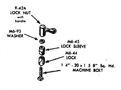
Those two parts, M6-44 and M6-45 are the same part number used on most of the 10" and 12" lathes. See this clip from a parts drawing for Craftsman 101.07403/101.27430/101-27449 12" lathes:

Lathe_TS_Lock.jpg

I checked several other models also: Same part numbers, even the Craftsman Commercial 12" under-cabinet drive lathes. Only the Atlas 10E was different. Both parts are still available from Searspartsdirect.com, so they are probably available from Clausing. Or could be found on E-bay as Atlas/Craftsman 10-12 lathe parts. That the part number begins with "M6" I suspect they are also used on the Atlas built 6" lathes, but I do not have those parts lists in my library so I cannot confirm.

Spiral_Chips
 
Wheels17 it looks like you and I are thinking along the same lines... however, since I'm still trying to reassemble my machinery here, I plan to "cheat" a little and make these parts on a lathe and one of the big vertical mills at the college. I'm wondering whether I should "notch" it on both sides, or just one, like the original appears(?) to be. Also, I am still struggling with the concept of the recess on the lower one... does the square head of the bolt fit all the way into it, or does it straddle the head of the bolt, or what? It looks like the head would be totally enclosed, right?? :distrust:

I'm thinking I can use a mild steel bolt, make the center spacer of medium hard rubber, and use aluminum for everything else including the knob/lever assembly on top. I'll probably be a little creative on the design of the knob rather than trying to duplicate the lines of the casting. Just how strongly does one have to clamp down on this knob? :cautious:

Of course I'll also be thinking eventually about the knob assembly for the eccentric as well, but that's a story for another day. :confused:

Froggie
 
Spiral_Chips, my Google-Fu isn't working... I can't find the page you clipped out to show the picture in your last post. Which sub-assembly did that come from and what do they call it on the lathe?

Never mind... I looked it up by the Mill model #. The two jamming pieces are there (your #1 and #3, but everything else is NLA. :(

Wow, $97.96 for the four lock sleeves... I'm getting a lot more serious about making them myself now!
 
Last edited:
I went back down and looked at my parts labeled #4. They are steel, so perhaps not original.

Mine are steel also.

Makes sense to me. But if it is really an M6-45 then a total of four are required, two for each of the upper lock assemblies, but the M1-60 end casting uses only one.

Spiral_Chips

I would count a total of 5 M6-45 and 3 M6-44 including the set used for the M1-60 Arbor Support assuming 2 M6-45's are just used as spacers (Wheels17 #4) either way the total is wrong, but this wouldn't be the first error found on Atlas diagrams and probably not the last.

does the square head of the bolt fit all the way into it, or does it straddle the head of the bolt, or what? It looks like the head would be totally enclosed, right??

The square recess allows the head of the bolt to fit flush. The head of the square bolt does not extend beyond the bottom of M6-44. There isn't a whole lot of material on the edge of M6-44 where the pointy ends of the square head are.
 
As Spiral_Chips stated they are the same as used on my Craftsman 12" Lathe in the Tailstock. The top M6-45 is just a spacer. In my mill both of the M6-45 are the same. I would think that if you made a replacement you could just make it double length. I would also make it out of Aluminum and not steel. When clamping steel would have a tendency to make a indent in the overhead support. I have seen a post somewhere that on the M6-44 replacement someone just used a endmill across the end of the new piece. It only enclosed 2 sides of the bolt head.

I haven't used my mill much with the overhead support but when I did I didn't have to clamp the end very hard. Also on my lathe it is the same for the tailstock ram when clamping it.
 
Back
Top