Edwards Radial 5 build thread --- PHOTOS!

Started on the Edwards 5 the other day. Looking forward to more progress photos from @JRaut. Have been really enjoying his posts. It inspired me to start mine. I drew the CAD models in Fusion360 a couple years ago but never started the project until I saw this thread. Thanks @JRaut for sharing. Can't wait for the next installment. I will post my progress here as well.

1642048433711.png
1642049094743.png
 
Last edited:
Hey great timing, @dbonetti!

It's been over a year since my last post, and I'm finally providing an update tonight!

Congrats on starting your build. I'm more than happy to answer any questions you may have along the way.
 
Episode 16.1 || Cylinder Heads (part 1)

Well, I’m embarrassed to say it, but it’s been over a year since my last installment. I’ve finally made time to keep working on the Edwards in the past weeks/months. I started the cylinder heads over a year ago and am just finishing them up now, so some of the early details are a bit fuzzy. Anyway, here goes…

Making these heads took more setups / operations than any other component in the build so far. Maybe combined. There’s one primary difference between the heads as depicted in the drawings and the way I built them: I used Beryllium Copper valve cages, whereas the drawings depict the heads as being made of a single chunk of aluminum. Problem is, how the drawings show the thing is essentially unbuildable (because of the inclined valve stem extending up above the top of the head), and because it’s all aluminum, seems to me it’d wear out pretty fast. The images below from Fusion show how I actually made them (i.e., with the valve cages).
Fusion_01.PNG Fusion_02.PNG

Alright, with all that out of the way, here’s the process I used to make these bad boys.

It took about a million setups to complete everything on the head, so before I set to machining anything I laid out my anticipated order of operations. This changed a couple times throughout the process so I just printed out new ones as appropriate.
IMG_1141.JPG


Setup #1: Turn the OD of the cylinder head. Bore out a couple steps to match the piston and sleeve diameters. And turn a 20-degree cone in there too to match the piston dome. I grabbed a broken end mill from my bucket and ground up a special ‘boring/facing’ tool to do this.
IMG_1054.JPG IMG_1055.JPG

IMG_1056.JPG IMG_1057.JPG


Setup #2 & #3: Mill the flats on the OD of the heads for the intake / exhaust ports. I didn’t take any pictures of the machining, but here are the results so far.
IMG_1063.JPG


Setup #4: Deck the top of the head with a fly cutter. Drill / counterbore for #4-40 SHCS to match the bolt pattern everywhere else. NOTE: this is a non-uniform bolt pattern. I messed that up on my first stab at making the crankcase.
IMG_1065.JPG IMG_1066.JPG


Setup #5 & #6: Clamp the head in my sine vise (set at 20-degrees), which itself is clamped in my main milling vise. Mill a slot and drill/tap a hole for the rocker bracket. Drill/ream/counterbore for the valve cage and spring. Do this for both the intake and exhaust sides. Center finding was difficult -- in the y-direction, I swept it with an Indicol, but in the x-direction I just lined things up to the edge of the part best I could with a sharp tool.
IMG_1067.JPG IMG_1073.JPG

IMG_1070.JPG IMG_1071.JPG


Setup #7 & #8: Flip the part over, and use the same 20-degree sine vise setup. Carefully center-find on the reamed hole. Use my Wohlhaupter UPA3 boring head to bore out the intake/exhaust holes to accept the yet-to-be-made valve cages. Use the ‘automatic facing’ feature of the UPA3 to face off the bottom of the hole (perpendicular to the bore) at the correct depth.
IMG_1129.JPG IMG_1135.JPG


Setup #9: Things are getting weird. Clamp the head in a grinding vise; clamp that grinding vise in the sine vise (still set at 20 degrees); that sine vise is still clamped in my milling vise. I had to do it this way so I could clamp on the intake/exhaust flats, rather than trying to clamp onto the curved OD surfaces of the head. Drill / counterbore / tap the pocket for the glow plug. I did the counterbore with an endmill. Strictly speaking, the bottom of that hole isn’t quite flat. But I reckoned it was good enough, as the glow plug seats on a malleable copper gasket/washer. The standard thread on these small glow plugs is 1/4-32; I didn’t have one of those on hand so I had to order one.
IMG_1136.JPG IMG_1137.JPG

IMG_1138.JPG IMG_1142.JPG


To be continued on next post…
 
Episode 16.2 || Cylinder Heads (part 2)

Continued from last post…

Setup #10: Clamp the head in a grinding vise, and clamp that grinding vise standing up in my main milling vise. Mill the airflow slots in the top of the head using a 40-thou slitting saw. I took the full 250-thou depth in one pass. Can’t do any more on the heads at this point until the valve cages are machined and installed.
IMG_1152.JPG


Setup #11: Back to the lathe, now with some Beryllium Copper** chucked up for the valve cages. Turned the rough overall OD, then finish-turned the stem to a hair under 0.250” so it can slip through the reamed hole in the head. I used a hacksaw to part the valve cages off. I do this often, even though some people say not to. Lathe is off and a piece of wood is down to protect the ways if I cut through unexpectedly. This stuff turns EXCEPTIONALLY well and takes a very good surface finish. Nice, smooth, long strings that are easy to cleanup. The chips are reminiscent of aluminum, but with some of the ‘crunchiness’ of brass. I used a sharp HSS cutter.

**I know, I know. People say this stuff is toxic. The internet tells me that only the dust is toxic, and I wasn’t creating any dust, so lay off.
IMG_1161.JPG


Setup #12: Flip the parts around, hold them in a 1/4” collet, and turn them down to the correct length. The critical length here is the length of the larger OD portion of the cage, as that has to nestle down into the bored pocket in the head. 0.3975 is what I was shooting for -- nailed it.
IMG_1218.JPG IMG_1165.JPG


Setup #13: Back in the 1/4” collet on the lathe -- drill, ream, counter-drill (is that a word?) the internal features. Then with the compound swung over to 45 degrees, cut the valve seat. Note that I wasn’t all that worried about getting the angle exactly at 45 degrees; the valves themselves will also be cut at 45 degrees, but I’ll lap each of them in to the mating valve seat. A 0.125” gage pin fits perfectly in the 1/8” reamed hole with no slop, as it should.
IMG_1223.JPG IMG_1226.JPG

IMG_1228.JPG

IMG_1229.JPG IMG_1237.JPG


Set up for Setup #14: Take careful measurements of the valve cage pockets that are bored into the heads. I really, really like the split-ball bore gages. The one I’m using here is a Starrett 82B. I calibrated it to read 0 at a bore of 0.426”, and made sure to check that my micrometer read the same when measuring over the gage blocks. As I said earlier, I’m shooting for a 1 thou interference fit here, plus the use of Loctite 620. Hopefully that’ll be sufficient to keep them in place, I expect that it will.
IMG_1238.JPG IMG_1230.JPG

IMG_1235.JPG IMG_1236.JPG


Setup #14: Back in the 1/4” collet on the lathe. Finish turn the OD to the appropriate dimension. Each is tailored to the valve pocket for which it’s destined. I left a few tenths on each of them and finished them off with some emery paper to get them to size. I ended up within about 1 or 2 tenths on all of them. NICE!
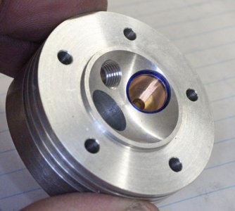
IMG_1240.JPG IMG_1241.JPG


Setup #15: I heated up the aluminum heads in the oven set to 450F (which is the rated temperature for Loctite 620), at which temperature the valve cage bores should grow by about 3 thou. Should be good enough to overcome the nominal 1-thou interference between the beryllium copper valve cages and their bores in the aluminum heads. After letting the head soak in the oven for 15 or so minutes, I spread some Loctite 620 on the valve cage, pulled the head out of the oven, and dropped/pushed in the cage. One valve cage at a time, no time for doing both without re-heating the head. Ideally I’d have the arbor press at the ready just in case, but our oven is in the kitchen and, well, my arbor press is not. Several of them were total disasters: I was too slow (I had to burn off the Loctite 620 with a propane torch to get the valve cages out). If I were to do it again, I would use a 2ish thou clearance fit instead of an interference fit; Loctite say that 620 can fill annular spaces of up to about 8 thou.

I didn’t take any pictures here. But trust me, it was a bit of a disaster.


Setup #16 & #17: I drilled /counterbored the intake and exhaust ports with an end mill. Then drilled / tapped the holes to bolt on the intake/exhaust headers. I used an endmill for the 1/4” through-hole because of the inclined interface between aluminum and beryllium copper.
IMG_1857.JPG IMG_1858.JPG


Setup #18: The last step was to mill the remaining cooling fin slits. I was planning on doing this over at the rotary table, but it was easier to just use the (very) modest 2-axis CNC capabilities of my Bridgeport EZ Trak. I used the same 40-thou slitting saw as before.
IMG_1861.JPG


Et voila, c’est fini!!! That was a long one!

IMG_1862.JPG

IMG_1863.JPG


Side notes:
1) I’ve only finished one of the heads. The remaining heads still need the slits done. I was antsy to get an update published here because it’s been so long.
2) I can’t seem to find one of the heads. I’m really, really crossing my fingers for it to turn up one of these days. I’d hate to have to make a new one.


I’ll hopefully post another few photos in the coming days of my overall progress so far. It really is coming along. I’ve got finishing this motor on my 2022 to-do list.


TIME ON CYLINDER HEADS: 61 hours
CUMULATIVE TIME: 329 hours
 
Glad to see you back at it. Possibly we share the Startandstopicytus disease that seems to inflict radial builders LOL. I had a handful of nagging issues that needed attention & it was just slow sledding. Hopefully I'm solved the last one which is pushrod tubes - thankfully something you Edwards builders don't have to deal with.

**oops you posted just as I was typing **
Anyways, aside from the ramble, I also installed bronze valve cages in my aluminum head. They were just a slide fit retained by high temp Loctite retainer so as not to distort seat I already have vacuum tested. Its a good thing I experimented on a dummy part because what caught me off guard was how fast the Loctite kicked. There is something about the bronze or combination that accelerates the cure big time. if Ientered slow & dawdled a bit, I would not have made it to the seated position. Much different than typical steel alloys.
 

Attachments

  • IMG_2376_edited-1.jpg
    IMG_2376_edited-1.jpg
    131.1 KB · Views: 20
Awesome work from one rc modeler to another. I start and stop on my 1/3 scale Cub build regularly and about to start year 5 but its a hobby....

Here's something that needs a flat 4 four stroke ( which I have).

20211218_140137.jpg
 
Awesome work! 300+ hours is no joke. My 150 hour steam engine took me 2 years.
 
One of my next steps will be working on the top end valve train components.

I had a hell of a time earlier in the build trying to put snap-ring grooves into hardened dowel pins. The rockers rock on 1/8" hardened dowel pins, which are prevented from sliding out of their housing by a small snap ring on each side.
1642170157014.png 1642170054950.png


While brainstorming alternative ways to cut the grooves in the dowel pins (a total of 20 grooves altogether) I came across these groove-less snap rings while perusing McMaster. Apparently you just slip them over the shaft; they're 5 thou undersized on the shaft diameter and extra stiff, so they just grab on using friction once you release them.
1642169854343.png


Has anyone used these before?

Anyone foresee any issues using them in my application? They say they can take a thrust load of 10 pounds; standard snap rings for the same shaft diameter can take up to 60 pounds. My application has (essentially) zero thrust load, so I'm thinking I'll at least try them out.

The only potential problem I really see creeping in would be if these things are prone to vibrating loose.
 
Back
Top