Edwards Radial 5 build thread --- PHOTOS!

I would personally want the snap in kind. You don't have side loads but you do have a lot of vibration. Wouldn't hurt to try what you have there.

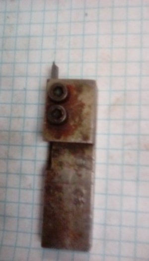
If you need to machine the groove, I recommend a ThinBit Groove-N-Turn tool from Kaiser. They aren't cheap but the quality is top notch and it is extremely versatile as you can purchase inserts for grooving (at multiple depths), threading (60*, 55*, ACME, etc.), chamfering, O-ring grooving, radius grooving, etc. All are available for custom order in 1 thou increments.

I bought a 1/2" Shank, right hand cut (manual lathe) LGS12R for a job I was doing at home and was just super impressed by the whole system. You'd want to look at a LGT012D2R insert (0.0120" +0.0009/-0.0000 width of cut, 0.036" DOC, carbide for steels, sharp corners).

I want to say when I bought this a couple years back, it was just under $100 for the holder and $12 per insert or so. I've found that because the inserts are designed for side turning as well as grooving, they are extremely tough unless I accidentally jam them into the part :rolleyes:

Also for all you carbide haters out there, you can get the inserts in HSS :)

No affiliation with this company, just impressed with their tools and for once I got a pro level tool in a size that was usable on a hobby machine.


Amazon links below. You might find better prices through a distributor. Some distributors marked it up 50% because I was a new customer though so be careful.


Last edited:
Could you make the groove a little wider? i.e Dremel cutting disc?
 
When I was putting grooves in dowels pins earlier in the project, I tried:


1) Using a Micro 100 solid carbide grooving tool. I ended up breaking 2 or 3 of these at something like $30/each. The dowel pins were just too damn hard, even for the solid carbide tool.

2) Using a Dremel with the thinnest cutting disc I could get my hands on. This is the solution that ended up working best, but the cutting disc wears away very quickly and unevenly. So the bottom of the grooves turned out half-round rather than squared off.


I think I've tentatively convinced myself to use these 'captive pins' with a head on one end, and double-up the groove-less snap rings on the other end. If things start shaking loose I'll revert back to the standard grooved snap ring and either use a slitting disc or try @macardoso's THINBIT solution.

1642172307007.png 1642172329250.png


1642172361659.png
 
Alright, 4 of the 5 heads are done.

I still can’t find #5 to finish it off, but it’s bound to turn up one of these days. I’ve no idea how I could possibly have misplaced it.

E179E031-833A-42E7-8205-0CCE7209CFB9.jpeg
52CF3433-E442-4500-8574-214275F6DE5D.jpeg
3BA047E2-39FF-421E-A3F0-A7047B0B467F.jpeg

I’m gonna have to make a stand for it pretty soon here.
 
Great work @JRaut . Looks awesome.
I had to rebuild my crankcase this weekend due to mistake in my drawing. I machined one cylinder tonight. Hope to finish the rest this week.
 

Attachments

  • 20220118_214517.jpg
    20220118_214517.jpg
    113.7 KB · Views: 32
  • 20220118_214453.jpg
    20220118_214453.jpg
    125.6 KB · Views: 28
  • 20220118_213347.jpg
    20220118_213347.jpg
    165.4 KB · Views: 32
@letmeatthem

Welcome to the group!

Brian
 
Episode 17 || Valves

I spent the past couple weeks making up the 10 valves -- 5 each for intake and exhaust. Ten identical parts is about as close as I get to a ‘production run.’ So best I could, I tried to make use of a few jig-type things along the way.

They’re made from 416 Stainless Steel. Man, that stuff is an absolute JOY to machine. It machines beautifully with HSS and a nice as-machined finish is easily achieved. I’m going to use this stuff more often.

The geometry is not complex. But these valves are small so I had to be careful about things flexing.
1643251766375.png 1643251752611.png


First things first, the valve part of the valve transitions to the stem part of the valve in a nice sweeping curve. I took the time to make up a little collet adapter so that I could hold a square lathe tool blank in a Kuhlmann (Deckel) single-lip cutter grinder collet. With that, I was able to grind up a nice tool with the right(ish) nose radius. Took me a few tries, but I got it sorted close enough.
1643251806748.jpeg 1643251828869.jpeg


Then over to the lathe. Turned a little spigot on the end of the 1/2” SS bar, added a center, and brought in a live center. Then turned the overall OD to the 0.4” valve body diameter. Within a tenth on a non-critical dimension? I’ll take that all day.
1643251890669.jpeg


Then I turned the 1/8” valve stem with my freshly-made turning tool. Got out the last few tenths and polished it up with some emery cloth and WD40. I didn’t bother covering the ways, as the grit is all in a slurry that stuck to the emery cloth and part, which I wiped off.
1643251911685.jpeg 1643251925649.jpeg


With the compound swung over at 45-degrees (which matches the valve seats I talk about in a previous post), I put on a 50-thou valve land. Looks nice, don’t it?
1643251948703.jpeg


I’m not too proud to use a jeweler’s saw / hack saw for parting off at the lathe. I keep a piece of scrap OSB close by to put on top of the ways. That way the saw hits the wood instead of the ways when I finish the cut. Had to be careful with the jeweler’s saw, that’s a heck of a lot of stickout on a 1/8” diameter rod.
1643251972256.jpeg 1643251987071.jpeg


I wanted each valve to be the same, more or less, so I made up a little spacer thingy to be used when facing off the ends of the valves.
1643252009911.jpeg 1643252037823.jpeg


Then another little spacer thing to be placed inside the collet (actually was a spare valve seat I didn’t end up using), used to trim the overall length of all valves. I’d have used a collet stop if I could, but my lathe uses 3AT collets, which don’t have internal threads to accommodate a collet stop. Set my micrometer stop for my lathe carriage and trimmed all valves to the same length. They came out to be within about 5-10 thou; not as close as I expected, but plenty good enough.
1643252059310.jpeg 1643252073064.jpeg


Last step in making the valves was to cut in the pocket for the valve retainer lock thingies. I used an HSS parting blade. In order to reduce tool pressure as much as possible (to avoid deflection in the super thin 1/8” valve stem), I ground it dead sharp with a highly positive rake angle. I then used my micrometer stop to help me position the parting blade to the right location for each side of the pocket. Takes a loooong time to get that all dialed in; maybe it’s time to get a DRO…
1643252095745.jpeg 1643252107487.jpeg


The pocket was too small to get a regular mic in there, so I used the opportunity to break out my new-to-me 0-1” Mitutoyo blade micrometer. Worked a treat!
1643252127709.jpeg


And there we have it! Ten valves over and done. I intend to lap each of them into a mating cylinder / valve cage, but will push that off until a bit further down the road. A quick spot check suggests they match very nicely with the valve cages in the cylinder heads, even without lapping them in yet.
1643252149780.jpeg 1643252160842.jpeg

1643252179418.jpeg

Next on the list will be the valve springs, retainers, retainer locks, rocker adjustment buttons, push rods, etc.

TIME ON VALVES: 16 hours
CUMULATIVE TIME: 342 hours
 
Last edited:
Back
Top