Enco 110-2031 Lathe, wiring setup

You could probably make a bracket out of light sheet metal- that is probably what I would do
Those switch assemblies get a lot of cycling and tend to fail fairly often. They are not usually stocked after a few years- if you can put one together with off the shelf parts plus homemade pieces all the better
-Mark
 
Last edited:
I'm pretty confident I can build one; I only need to know what it's supposed to look like. It would also be nice to know what microswitches are used, as I'd rather not pay >$20 per from Grizzly when they're almost certainly <$2 per from Digi-Key.
 
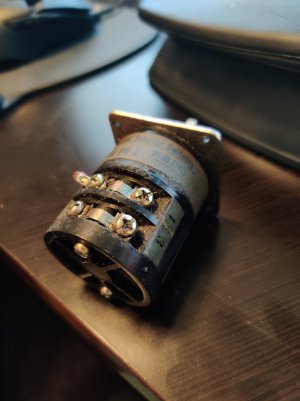
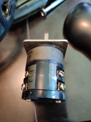
Jackpot! This is the original switch:

IMG_20210619_193217.jpg

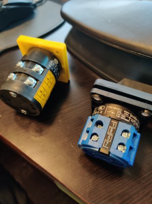
And these are apparently a couple potential replacements acquired by the previous owner (who is sadly no longer with us, so I cannot contact them for information):
IMG_20210619_193233.jpg

Neither of these are exact replacements, but the bolt pattern and shafts look like they're pretty close matches. Worst case, a new face plate with the right bolt pattern could easily be created from sheet metal.

The one on the left is an HZ5B-10 which is apparently very common for this type of lathe.

The switch setup on this lathe looks superficially very similar to a Grizzly G4003G.

The wires coming into the switch are labelled 3,4,5,6; is there any way to know how the switch should be wired (for example, 3-4 forward, 5-6 reverse)?
 
Last edited:
I'm going to peruse the diagram for the G4003G - so far I haven't come across an Enco diagram that covers the 24 volt, 2 contactor control system
with the single round switch like yours. Fortunately, it's a low voltage system so you could experiment without too much risk
 
Last edited:
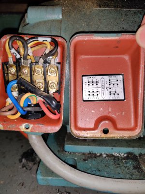
One more photo, this one of the motor wiring. The diagram doesn't make sense to me, but I imagine that the folks here with more experience might be able to make heads or tails of it. Just to confirm that the motor is also wired for 220v, as the 24v transformer is.

IMG_20210619_203322.jpg
 
Yes it looks like a 220 volt configuration- the blue one N.C. and taped up like that is the clue. It would be connected for 110v
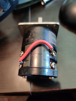
So back to the switch issue- is the original switch broken? Can you shoot some more pictures of it? I think I see jumper wires
 
Last edited:
Hooray! Just found a diagram for the 2031 drawn by another member: (courtesy of Steve1750, posted May 14, 2015)
 

Attachments

  • Enco Lathe 110-2031 wiring.pdf
    16.8 KB · Views: 23
The two contactors are wired in such a way that they lock each other out to prevent both being pulled at the same time, which would put a dead short across the incoming power line. There are actually two electrical lockouts: one NC contact on each contactor and also, at least in the twin microswitch case, at the direction switch for FWD
It looks like they may have used two types of switches; the round one like yours or the pair of microswitches. Maybe they made a change during production? Anyway it should be fairly easy to figure out the connection
 
Last edited:
IMG_20210620_091213.jpgIMG_20210620_091221.jpg

The jumper goes from 4 on one side to 2 on the other side; the new switch has terminals 1-8 instead of two pairs of 1-4.
 
Back
Top