Enco 110-2031 Lathe, wiring setup

Do you have a multimeter?
A resistance test could be performed on all the terminals
Put the rotary switch in the center position, pick a contact to start with and test continuity between every other contact
You should not have continuity between switch poles in the center position
Select the forward or reverse position on the rotary switch and repeat the continuity check on all contacts of the switch and record the results
You can then ascertain the pin out of the rotary switch , the circuit will be simpler to wire from there
This ^^^^

The numbers are irrelevant except to tell you what pole they are in the switch. In addition to a VOM a set of jumper wires with alligator clips are quite handy for this kind of thing, if you get it wrong they are easy to pull off when the smoke starts coming out;)

Also, drawing your own wiring diagram is a good exercise in getting to understand what's going on. Above all, DO NOT assume numbers, colors, or anything else will tell you what's going on, learn some basic electrical theory (if you haven't already) and use a meter to verify what's going on.

John
 
As I pointed out earlier, because of the fail-safe connection of the contactor coils you can't really smoke anything. It will either work, work in one direction only, or not work at all.

Edit: I'm not so sure this is correct- see post #28
 
Last edited:
So this existing switch is labelled "15A PN-1" which actually has a couple google results for what looks like this exact switch. Interestingly enough, this switch has one clockwise position, but *two* counter-clockwise positions. Based on the set screw in the shaft, however, it seems to me that only one of the counter-clockwise positions would be used, along with the center position and the clockwise position.

The two new switches seem to be two, stacked, completely independent switches, In the counter-clockwise position, terminals 1-2 are connected, and 5-6. In the clockwise position, 3-4 and 7-8 are connected. Edit: 1-2 and 3-4 are on the first ring, 5-6 and 7-8 are on the second ring).

The original switch is... harder to characterize (especially because it is presumably malfunctioning). I am also confused by the presence of the jumper wire between the two switches (assuming it's laid out the same as the new ones).

I also seem to have a problem of shaft length. The original switch's shaft is long enough for the set screw in the shaft to catch it, the HZ5B-10 switch definitely is too short, and the blue switch (LW26-20) is *barely* long enough (it'd half-catch it, which may or may not be enough).
 
Last edited:
You can wire up a simple dpdt switch to make the machine work and make the parts you need to fix it.

John
 
I guess the major question I have is, how would I wire up a DPDT switch? If I knew that, I could wire up the rotary switch. I guess what I'm hoping is that someone will know which numbered wires need to be connected for forward/reverse.

I assume that the contactors are set up as an H-bridge, and that of the 4 wires to the switch, two will power one contactor and 2 will power the other contactor; the schematic, however ("Enco Lathe 110-2031 wiring.pdf") shows only 3 wires to the switches, not 4 as mine has. The provided hand-drawn wiring diagram is the same (3 wires to the "micro switches" instead of 4).
 
Last edited:
This is where the jumper wires will come in handy. Last time I did it for my Bolton I just used trial & error till I had it figured out.

Sorry I can’t be of more help but I’m sure you’ll get it sussed out in no time with a meter and some jumpers.

John
 
I was looking at this again and it looks like the schematic in post 17 isn't an exact match to your machine. You have a small Omron relay in there as well which isn't on Steve's diagram. There is also a motor start relay which isn't shown either.
Probably at this stage it would be good to start tracing the wiring and draw an accurate diagram that shows how that small relay is tied in
That's what I would do- apparently your system was not documented from the factory and was probably a limited run

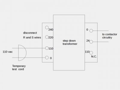
The safe way to test this thing would be to disconnect the transformer input leads and run a temporary 110 volt ac power to the step-down transformer's 110 volt input tap- no main power connections. This will power up just the 24 volt control system.
Then you could experiment with connecting the wires 3,4,5, and 6 until you get the contactors to operate one at a time. There's no mistaking the loud clack they make when they pull in. At that point if you can't get it to function then you would need to start tracing wires
 

Attachments

  • Testset1axz.jpeg
    Testset1axz.jpeg
    49.8 KB · Views: 9
Last edited:
Any chance this motor would run on 3-phase? I could just slap a Chinese VFD in here and call it a day?
 
yes this motor quite possibly could be used on 3 phase, it would require removal of the OEM controls
you would need to remove the capacitor and tap the motor WYE, before introduction of the VFD
 
Last edited:
Back
Top