Enco 110-2031 Lathe, wiring setup

No, there is no clicking when the switch is engaged (in either direction).

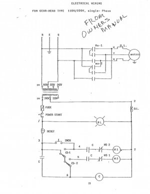
I have upgraded my membership, and I have examined that exact document. It doesn't, however, seem to match the wiring setup my lathe has.

If I decide the best option is to simply convert the whole thing to 3-phase, where does one source a 1.5/2hp 3-phase motor? The VFDs can be had from Amazon, but I have no idea where one would purchase a motor like that...

I found mine on Craigslist but they are available from lots of different sources.

If you've never used a lathe with variable speed it'll be a revelation for you. Being able to dial in just the right speed by turning a knob is really convenient compared to changing belts only to find out that you need something in between two settings.

If your machine wasn't running when you bought it you could easily have a bad component in your control box, especially if things were torn apart when you got it chances are pretty high that someone else tried and didn't succeed in fixing it. There's really no substitute for going through each component methodically until you find the bad part, then you have to find a replacement....

You could just install a drum switch and bypass the contactors all together, for me it's just better to switch the motor out now rather than fiddling around with 75-year-old technology.

YMMV,

John
 
In my case, it's only 45-year old technology :) I've never actually run a metal lathe before, so this is all a revelation. I haven't even started looking into the Rockwell 21-100 that I picked up alongside this thing.

I've mapped out more of the schematic here, and I'm now convinced that #3-#6 will have to be connected by the switch to power the relay, which will then allow power to run to the contactor (the right-hand one, which is connected to the circuit breaker). What's weird is that once that happens, the relay will power itself, and shutting off the fwd/rev switch will leave the relay powered. I'll draw up the schematic as I have it now, and see if someone can make some sense of it.

One of the things I don't get is that the two contactors have 12 contacts each; 3 pairs for the motor (in-out), plus 2 pairs for... something?, plus one more pair that I assume runs the coil. The only ones I'm sure of the locations for are the pairs for the motor. Anyone have a pinout for these things?
 
I worked out enough of the wiring diagram to conclude that the only way the little Omron relay will be energized is by connecting #3-#6 at the fwd/rev switch (#3, #4, #5, #6 all go to the switch, #1 and #3 go to the e-stop). The thing I don't really get is why the relay is set up to "latch" itself; once it's on, it'd stay on until the e-stop was triggered. Does this sort of wiring diagram seem familiar to anyone?

1626450628682.png
 
Last edited:
I just worked up the courage to momentarily jump wires #3 and #6 (as labelled in the schematic), and I found that as long as I don't hit the e-stop or unplug the lathe, everything works as expected, forward and reverse. This means that my schematic is probably at least mostly correct (as much of it is there, anyway), and the contactors and relays are working correctly.

The wiring still doesn't make any sense to me, though, and poking wires around in the 220V wiring cabinet every time I use it is... special.
 
Last edited:
your transformer is currently tapped for 220v operation- don't plug this lathe into 120v without tapping it for lower voltage
the 4 red wires (assuming3, 4,5,6) are for directional control
one or 2 wires may have constant power, the other 2 indirectly pull in the forward or reverse contactor respectively

it looks like the system is intact
you can test operation by assuring there's no wires making contact with the frame
isolate the (4 red wired assumed to be)3, 4, 5 ,6 wires so as they cannot touch each other or ground out against the frame
add some single phase 220/240 volts through the power cord
test voltage from 3 or 4 to ground, if you have voltage present, this is the control power- a pairing of other 2 wires determine direction
if you were so inclined, you could disconnect power from the machine and connect (the assumed pairing) wires 3 and 5 together, and plug the power cord in after making sure no feeds are engaged.
WARNING: if the system is functioning correctly, the spindle may rotate upon plugging the machine in - if not prevented from doing so by the emergency stop switch being activated !!!!
the e-stop is generally a maintained contact normally closed switch, that when activated, stops flow of control voltage and operation.
knowing this, you could use the E-stop to turn off and on the spindle for troubleshooting purposes
test the other 2 red wires for voltage to ground, if the spindle doesn't turn

there are 2 cam operated microswitches on my lathe for directional control from the apron switch, yours may have had a slightly different arrangement like a 3 position switch in the absence of an apron switch, but the idea would be the same.
a DPDT toggle switch, could be retrofitted to quickly restore operation
a Drum Switch could be retrofitted easily
a pendant station could be wired with 2 buttons for directional control
OEM parts may be available somewhere, but it may be difficult to find the actual control switch for your machine- a retrofit may be in order

(edited for better information)
Also, and this is important!!!!

You need to put oil in for the spindle bearings before you run it or you will be sorry very soon. The oil fills on these machines are accessed by lifting the belt/gear cover on top of the machine.

View attachment 369597

John
Where is the drain? I see a fill and drain on the quick change but
no drain on the headstock. (12X36 enco-110-2031 built 1991 serial 4251)
 
your transformer is currently tapped for 220v operation- don't plug this lathe into 120v without tapping it for lower voltage
the 4 red wires (assuming3, 4,5,6) are for directional control
one or 2 wires may have constant power, the other 2 indirectly pull in the forward or reverse contactor respectively

it looks like the system is intact
you can test operation by assuring there's no wires making contact with the frame
isolate the (4 red wired assumed to be)3, 4, 5 ,6 wires so as they cannot touch each other or ground out against the frame
add some single phase 220/240 volts through the power cord
test voltage from 3 or 4 to ground, if you have voltage present, this is the control power- a pairing of other 2 wires determine direction
if you were so inclined, you could disconnect power from the machine and connect (the assumed pairing) wires 3 and 5 together, and plug the power cord in after making sure no feeds are engaged.
WARNING: if the system is functioning correctly, the spindle may rotate upon plugging the machine in - if not prevented from doing so by the emergency stop switch being activated !!!!
the e-stop is generally a maintained contact normally closed switch, that when activated, stops flow of control voltage and operation.
knowing this, you could use the E-stop to turn off and on the spindle for troubleshooting purposes
test the other 2 red wires for voltage to ground, if the spindle doesn't turn

there are 2 cam operated microswitches on my lathe for directional control from the apron switch, yours may have had a slightly different arrangement like a 3 position switch in the absence of an apron switch, but the idea would be the same.
a DPDT toggle switch, could be retrofitted to quickly restore operation
a Drum Switch could be retrofitted easily
a pendant station could be wired with 2 buttons for directional control
OEM parts may be available somewhere, but it may be difficult to find the actual control switch for your machine- a retrofit may be in order

(edited for better information)
I have a problem with a Enco 110-2031 12/36 built 1991 serial4257 bench lathe where there is a delay in the machine stopping when is turned off from the apron.
It can take several minutes to go off and the emergency stop also will not turn it off. Reverse works fine, emergency stop also works when in reverse. It has been like this since new and at times it works fine. The fact the emergency stop does not work really puzzles me.
I tried metering the apron switches they seem to be OK the stop button also seems to be OK. I had someone look at it that Enco recommended to no avail.
 

Attachments

  • Scan3 (2).jpg
    Scan3 (2).jpg
    126.8 KB · Views: 2
Where is the drain? I see a fill and drain on the quick change but
no drain on the headstock. (12X36 enco-110-2031 built 1991 serial 4251)
Pop out the sight glasses to drain and run the spindle by hand. There is a lip inside and the bearing needs to rotate to “throw” the oil out of the drain.

If dirty, flush and drain with clean oil before refilling.
 
Pop out the sight glasses to drain and run the spindle by hand. There is a lip inside and the bearing needs to rotate to “throw” the oil out of the drain.

If dirty, flush and drain with clean oil before refilling.
My luck the plastic would break. Are new ones available? Also will this drain both ends of the spindle and how much oil is in there?
 
Back
Top