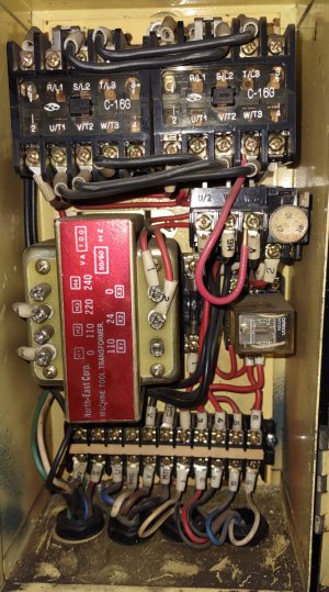
I found some photographs online and was able to put together what I think is an accurate representation of the low voltage section
Should be helpful- Connecting 3 and 6 momentarily should latch K3, then connecting 6 to 4 should give forward and 6 to 5 should give reverse.
There might be an open circuit somewhere, or the diode bridge D1 that powers K3 might be bad. Note: NC contacts on K3 not used
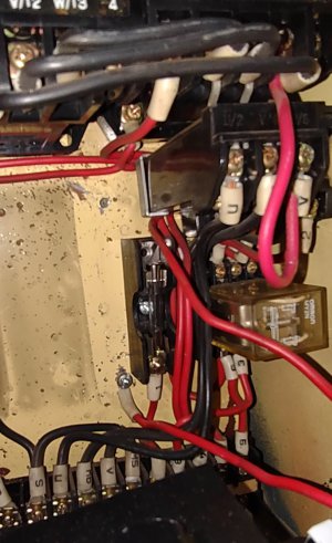
Was getting started and noticed something. The top of the fuse has no wire commented to it. There is a missing screw at the top of the fuse holding bracket. No wire, no screw. This seems messed up.
Let me know.
Thanks Danny
That would do it- I think it goes to either the transformer 0v terminal or terminal strip #1 depending on which one is missing
You must have removed it to replace the transformer
Never removed any wires in transformer replacement. I'm beginning to think that the folks that stored this lathe "played " with it. Sure glad it was a gift. I will look closely to see what I can find.
I'll report later.
Thanks Danny
Attached is a photo of the fuse wiring with the old transformer before I ever did anything. It appears to have never had a wire but the top screw was used to hold the old transformer in place. Is this the equivalent to the 0v connection on the new transformer? I read 0 volts to the fuse connections and #1 wires at the main terminal.
When I get a chance I'm going to do the best I can to "create" a schematic of the electrical system or I'm going to give up on this lathe and become a monk.
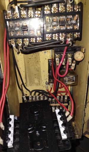
What does it look like now? Shoot a new photo please so I can see what you are seeing
The red "repair" wire that's looping down (and in the way of everything) could be shortened- that would make your life easier
Don't be afraid to push wires out of the way a little to see things better- just be sure the power is off first
One fuse wire should come from the transformer and the other fuse wire should go down to the main terminal strip #1
Both wires are marked #1
The fuseholder has metric screws most likely- I see a trip to the hardware store in your future
What were they thinking? I'm guessing they were planning to add a wire from the fuseholder to the box to complete the circuit but never finished the install
Yes that wire that's screwed to the back of the box needs to go to the upper fuseholder terminal- you'll need to extend it/replace it
Are you certain the transformer puts out the proper 24 volts? You measured it?
Don't want to burn out all your gear
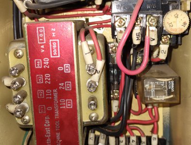
That transformer should be mounted in some way and protected from chips- that's a potential fire/shock hazard bro
If possible I would mount it on the side of the box and run the wires in thru a grommet
Yes the transformer is 24v.
It'll be tomorrow before I get back in the shop.
I'll keep you apprised.
I am aware the trans former needs remounted.
May add its own box.
This site uses cookies to help personalise content, tailor your experience and to keep you logged in if you register.
By continuing to use this site, you are consenting to our use of cookies.