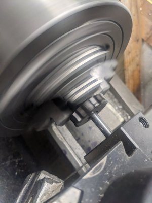
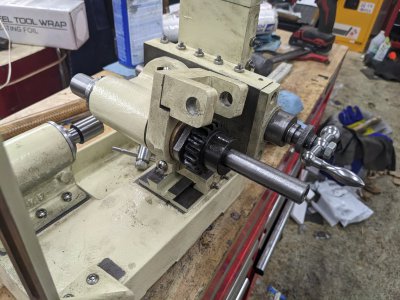
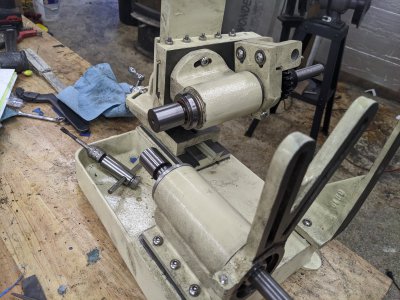
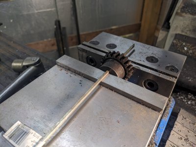
Erich's Benchtop Gear Hobber Project

0.969"-32 PTI, what?

Well there it is under American National Special (Unified Special) or "UNS"......
http://www.whittet-higgins.com/thrddim.php?id=1

I learned something today.... I can official shut off my brain!
Thanks Erich!

Brian
Yup! Two new threads for me this time :) N03 and N05 are "bearing retaining nuts" that all seem to have about 32 TPI that seems designed to match certain bearing sizes.
 
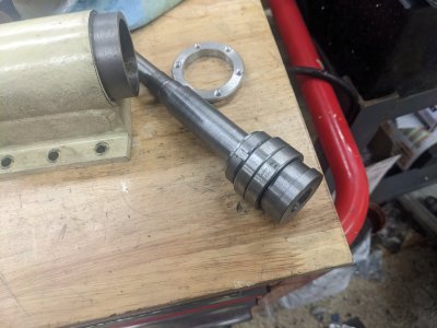
Alright, finished the hob arbor, and discovered a BIG mistake... I gotta think about it for a bit.

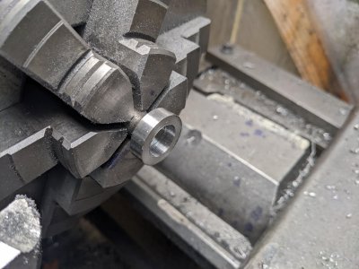
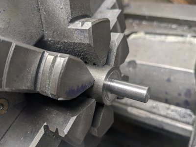
First, I finished up on the outside dimensions of the shaft, BUT I turned down the drive flange, since I'm not using it anymore. This means the bearing retaining ring doesn't need to be between the flange and bearings.
PXL_20221228_210725517.jpg

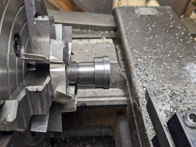
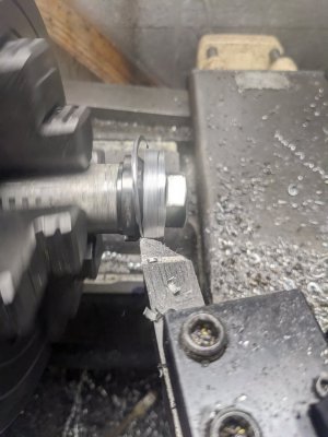
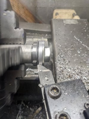
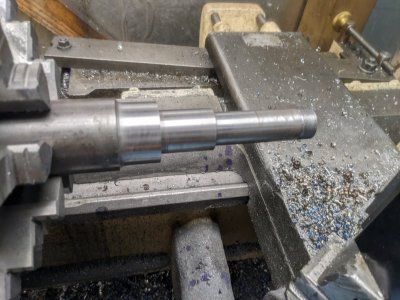
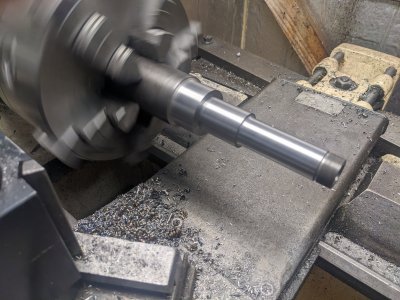
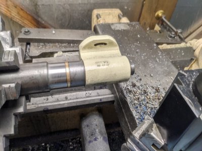
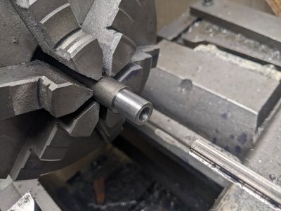
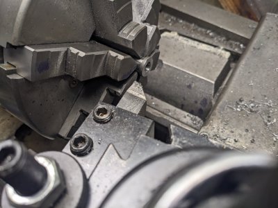
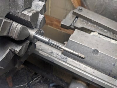
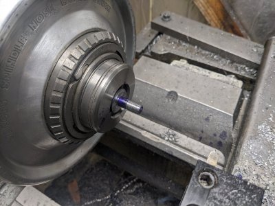
Here it is, all the turning here is done, and here is how the tool holder fits. I might need to ream it a little deeper, but I'm happy with it for now.


PXL_20221228_211229124.jpgPXL_20221228_211233781.jpg

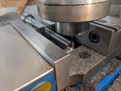
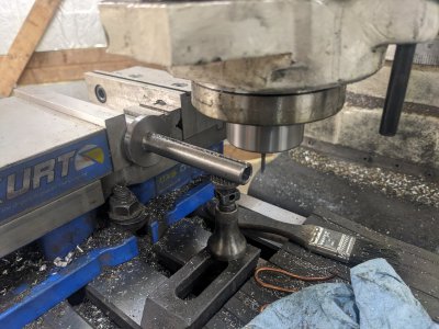
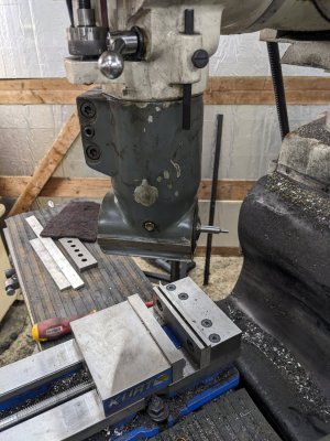
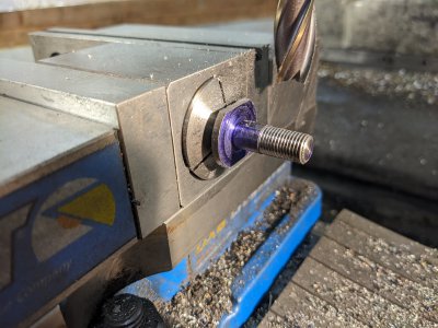
Next, I went to the mill to cut a keyway for where the gears go.PXL_20221228_212218487.jpg

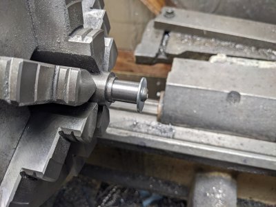
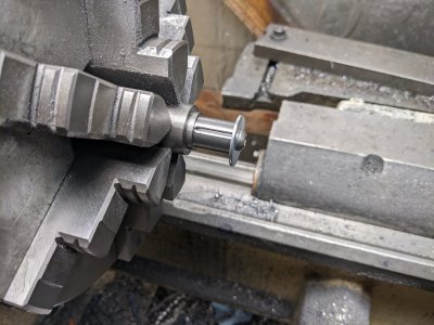
I had to turn down the larger bearing nut here, so I made a mandrel with a 5/8" bolt to squish it:

PXL_20221228_215554105.jpg

PXL_20221228_215554452.jpg

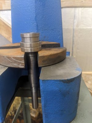
And, here I pressed the top bearings in place:
PXL_20221228_220529766.jpg

And installed the nut. Note it is backwards. It has a rubber retaining portion in it that I couldn't get to start on the slightly too tight threads. This shouldn't be a problem, the shoulder is still athe right size, and it clamps it right.

PXL_20221228_221003715.jpg

I got the whole spindle assembled into the housing, but forgot to take a picture!

BUT, here is my mistake. I went to start the other spindle, and realized I reversed the bearings! The larger bronze bearing is supposed to be on the drive side, and the smaller, plus retaining nut(another N05!) goes on the back.

SO, I have two choices; either remake the casting (which requires buying a new one, and new bushings), OR redesign it to have the retaining nut on the front. I'm leaning towards the latter, but I'm going to sleep on it.
 
I opted to just re-design/reverse the spindle instead of re-making everything. In the end, I have a happy outcome, but another problem that I have to figure out...

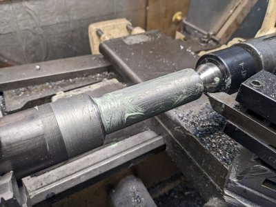
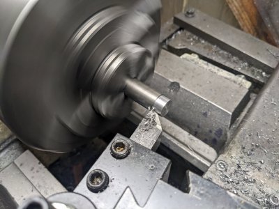
First, I found a poorly ground piece of HSS in my drawer to use as a roughing tool. I had to take 2" of 1144 down to 1 inch on this side.

PXL_20221229_182017718.jpg

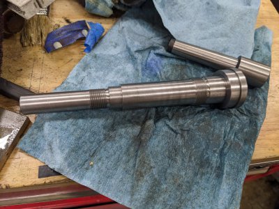
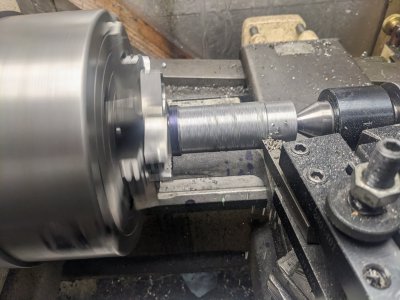
I then did the parts of the shaft that goes in the bushings, plus the threaded portion for the retaining nut, and cut an MT2 socket in the end, and drilled as far though as I could from this side:
PXL_20221229_195632123.jpgPXL_20221229_212607032.jpg

And it fit!
PXL_20221229_195625942.jpg

Next, I flipped it around to cut the 5/8 side the gears ride on. Started with roughing, then forgot go take a pic :)
PXL_20221229_215557334.jpg

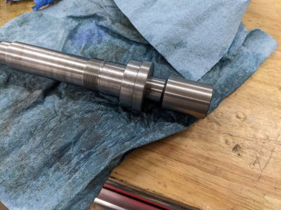
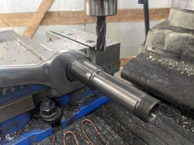
Cut a keyway:PXL_20221229_225459284.jpg

Next, I cut some flats so I can use a wrench. I meant to go for 1-7/16, but messed up on the depth of cut, and decided to just go for 1-1/4.

PXL_20221229_230543709.jpg

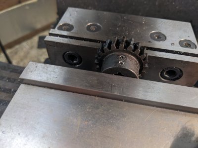
Next, I had to bore out a factory bought gear, which drives this shaft. I also cut a keyway. I think I need a set screw as well, but didn't cut one yet (and the plans don't say to have one!).

PXL_20221229_234533065.jpg

And here it is all in place:

PXL_20221229_235348300.jpgPXL_20221229_235352521.jpg

And here is my problem: when the feed is all the way forward, the end of the MT2 blank doesn't hit the end-line of the cutter! I am going to have to create some sort of holder for the gears that puts them far enough forward, ive got a good two or three inches of travel, so I'd like to be able to cut 2-3 gears at once.

I think I might make the shaft that connects to the arbor stick out quite a bit, perhaps one that just indexes off the current one, unless I can find an MT2 machinable arbor with a 3+" machinable section.
 
I didn't really get any work done today other than adding set screws to the keyed gear:
PXL_20230103_215249085.jpgPXL_20230103_215943193.jpg

The rest of my time was trying to plan next steps, and getting distracted by this thanks to @mattthemuppet2 PXL_20230103_224257267.jpg

It's going to lead to MORE side projects as the arbor support doesn't match the arbor or my mill, so theres a bit of mods to the arbor and support, but it was too good of a deal to skip!

BUT those are future projects fortunately, and won't block this one.
 
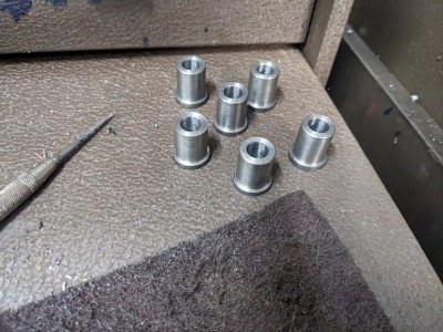
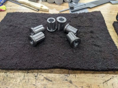
Just a small part today, but 6 of them :). This is one of the two parts to the quadrant gear holders. There aren't any plans for how to make these, so they are my design.

I started with some .750 bar, faced and turned the last bit for the gears down to 5/8.

PXL_20230104_230340724.jpg

Next, drilled and reamed to 3/8 for the shaft that goes inside of it.
PXL_20230104_231004063.jpg

After parting, they get flipped, and faced to length:
PXL_20230104_232407151.jpg

And here they are after those two setups:
PXL_20230104_233345285.jpg

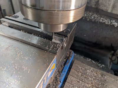
Next I just cut a keyway, since this one's job is to keep the two gears riding on it in sync:
PXL_20230104_234522040.jpg

And done!PXL_20230104_235219494.jpg

I'm hopeful I can start on the other sides of this tomorrow!
 
I spent the last few days working on the other half of the quadrant gear holders.

This has two parts to it, one side that holds the previous part in a rotating fit, and the other that bolts to the quadrant. It does not need to be concentric, which has some work holding advantages. As before, this is a my-design part that wasn't in the plans.

First, I turned down 1" stock to 3/8". There is a shoulder on it with a little raised ring to be a bearing surface. I made sure to match it to the length of the gear holder parts (though those are all within 2 thou of length, so are effectively interchangeable).

PXL_20230105_221625294.jpg

Next, I drilled and tapped for a 1/4-20 to hold this side together:
PXL_20230105_222103168.jpg

And here it is assembled:
PXL_20230105_222227061.jpg

PXL_20230105_222231918.jpg

As before, I'm making 6 of these, so there was a lot of repetitive work.

After those were done, I flipped them and put them in a collet chuck to turn the side that goes into the quadrant.

The shaft is a little under .400 (spec on the quadrants was .375, but I went way over on 3 of the slots, and way under on 2, I'm likely going to use my die filer to just widen all to about .400), and about .400 long before the 3/8" area I will end up single point threading.
PXL_20230106_225156349.jpg


After single pointing them, I made some 13/16" flats for a wrench:

PXL_20230107_210230259.jpg

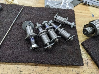
And here they are loosely assembled! An observant person would notice there are only 5! During the turning of the 2nd half, I had a crash which spun it around in the collet, ruining it. SO, I'm going to live with 5! I suspect I'll rarely use more than 4, but was making 6 as that is the most I can imagine ever using.
PXL_20230107_212329006.jpg

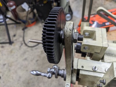
And here are a few pictures of it assembled with some gears:
PXL_20230107_213447707.jpg

PXL_20230107_213449780.jpg

And, a video of it spinning :)
View attachment PXL_20230107_213451957.mp4
 
I’m enjoying following your progress on this. Keep up the good work and keep posting


Sent from my iPhone using Tapatalk
 
So the list of things to complete is pretty short now!

1-I have to do the linkage from the hob spindle to the work spindle (which the above parts do the start of).
2- I have to make the work-holding and hob holding MT2 adapters. There will be a challenge there, as I have to make the work holding spindle particularly long (thanks to not doing the CAT20 holder, I ended up not 'wasting' as much room)
3- Mounting the electric motor
4- Figuring out how to drive the motor. It is a 12V 337W motor that I'd like to have with a variable power supply, but finding one is going to be a touch troublesome.

SO, lets continue on #1. There are a pair of universal joints that move the power from the big "L" shaped piece to the work-spindle. On one side, the arm holds the gear (at the L) and the other, transfers to the worm gear (which is the 20-1 reduction).

First, I wanted to get the Universal Joint "centers" done. This was a bit of an arbitrary choice, but makes the assembling of them as I go along possible.

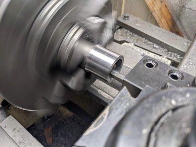
I started with a 1.5" piece of 12L14, turned the outside down a touch, and turned the inside to 1.125" long enough to make both of these:
PXL_20230109_220807282.jpg

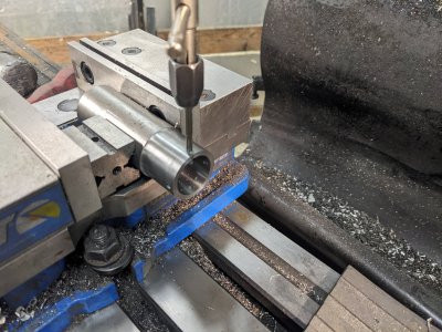
After that, I drilled/tapped the set-screw holes holes at 90 degrees (4 of them!) that act as the pivots for the universal joint.:
PXL_20230109_224112022.jpg

I drilled all the way through at each side, and used a square to line up the opposite side for the cross drilling, I believe I'm pretty darn close to perfect.

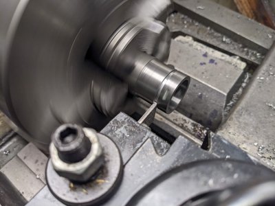
Finally, I parted it off:
PXL_20230109_224559455.jpg

I repeated the drilling/tapping/parting to get a 2nd one out of it, then used the surface grinder to get them down to thickness. I managed to not get a picture of that part :) After some deburring, they are done, though THAT picture is missing too.

After that, I decided to start on the worm-gear side.

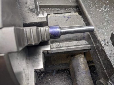
I started by turning it down to be a fit into the bracket it is going to ride in:
PXL_20230109_235238575.jpg

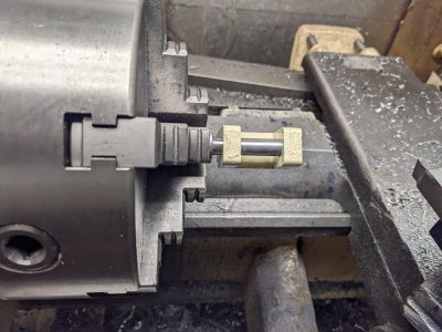
And you can see how it goes through here:
PXL_20230109_234356336.jpg

The worm gear rides in the center of that, and there is a set screw on a 2nd collar that holds it all in place (perhaps tomorrow's task!).


After getting that end finished, I flipped it around and started forming the Universal joint side:PXL_20230110_000442876.jpg

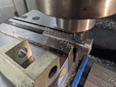
It looks a litlte weird, but what I did was turn and face it, then drilled it out with my largest drill bit, then went in with the 5/8" endmill in the tailstock to get it about the right size. In retrospect thats perhaps not the perfect idea, but it was nice to get that much material removed.

The worm gear is held from rotating with a key, so I cut that next. This poor 1/8" endmill has received a ton of abuse during this project, and managed at least 1 more, though I think it is getting dull (it wondered for the first time)! Either way, the keyway turned out good enough, particularly given how tight the gear is on the shaft.
PXL_20230110_001310805.jpg

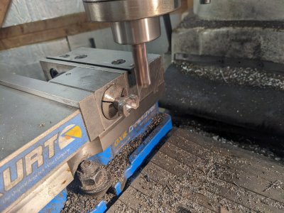
Next, I needed to form the 'fork' end. This was mostly just trying stuff to see how it would work out (I didn't spend much time planning this part!). First I did top-and-bottom with my 5/8" mill:
PXL_20230110_002456044.jpg

In retrospect, I probably could have increased stick out and done this with side milling, but I didn't think about it. Additionally, I needed it in this orientation for the next step, which is to better square up the 'insides' of the fork:
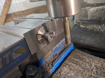
PXL_20230110_003117507.jpg

I suspect this is to prevent the forks from hitting each other (indeed, it says to spend some time with some files to round things over to keep it running smoothly, so I figure I'll be doing that anyway).

Finally, I used a center drill to make a sizable intent on each side for the grub-screws from the hoop to hit, and use as the pivot points:
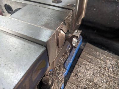
PXL_20230110_004018553.jpg


After a few minutes on the knock-off scotchbrite wheel, here it is, next to the parts it'll end up keeping together!
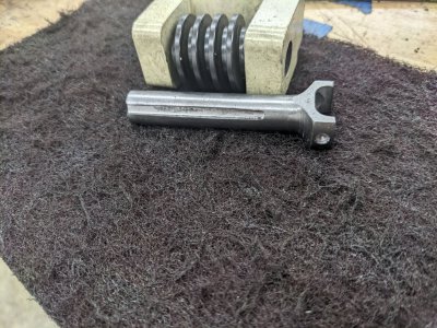
PXL_20230110_004353497.jpg
 
So, a couple of summers ago I needed a lot of power at 12v. Of course everyone wants 12v supplies, but no one wants 24v supplies. But if you dig close, some 24v supplies have remote control inputs for voltage and current limit. If they're switching supplies, just set them 12v and off you go.

In my case I ended up with three really nice old TDK 1500W 24v units for $50 ea. Had to replace a few fans, but otherwise fully functional.

I'll keep my eyes out for any more similar units...

A good xantrex or Sorensen adjustable runs for close to a grand now. Things are getting crazy for some of that used stuff...


Dan

Sent from my moto z4 using Tapatalk
 
Cool! Whatever you find would be appreciated! Otherwise I'm looking at a pretty sizable box for a transformer and speed controller in 1. This is the motor I ended up with: https://www.vexrobotics.com/217-2000.html
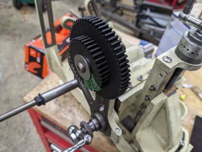
I found a cheap one at a local electronics store, and I know they are plenty torquey.
 
Back
Top