So I spent yesterday evening going over the plans as best I could, without some level of instruction or an assembly diagram, it is pretty confusing, and I think I found a few dimensions that are either confusing, or incorrect. It also does an annoying job of mixing radius and diameter in a few places. I got a feeling there are a few pieces missing from the drawings, so I think I'll have to engineer a couple as I go along.
One thing I'm particularly confused about is the dial mounts section of the feed screws, which doesn't really make sense/add up to me. BUT thats a problem for a later-date, and I can engineer something when I get there.
One thing I DID notice, is it is designed with an NMTB20 tool-holder for both the work holder spindle and the hobber holder spindle. I cannot for the life of me find a half-decent source of those, so I might find myself replacing those with something like MT2 along the way.
All that said, this looks like it'll be a fun kit to work on!
THAT SAID, I studied the base plate, and the 3 pieces that connect to it directly, and am pretty confident I know enough to get that done correct, AND understand what are the important dimensions/locations.
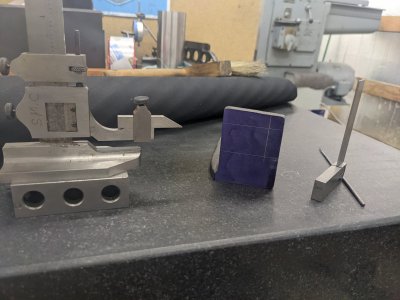
I started by filing casting marks off the base and hobber-spindle-housing I wanted to start by flattening the base, but need to get a very heavy vice off the shaper, so I can do it over there first

SO, I decided to first machine the hobber spindle housing, which has the hobber spindle (which holds a tool holder on one side, and has a drive pulley and gear on the other).
I started by facing the bottom flat, which is going to allow me to setup the important reference surfaces:

I ended up adding packing there a little later.
Next, I had to find the 'center line' best I could, which I did with a wiggler and by eye:

Next, I need 'zero' face on this side (the gear/drive pulley side) to base some other measurements off of. the sticking out part of the cylinder will have the quadrant arms on it, so that boss needs to be turned to this face. Also, this is the 'zero' for alignment with the "EL" bracket that holds the other part of the gear train.

Next, I squared up the sides, based on my 'center' point, so that the flanges are the same size on each side. This will be useful as indexing surfaces in the future I believe.

The plans call for a key-stock alignment pin, so I cut a 1/8x1/16 slot down the center. This should make sure this stays square to the other components on the base.

FINALLY, I flipped it up on its back side with a parallel against the indexing face I made earlier, and flattened the 'hob' side. This needs to be flat because I'm going to use it to index in the 4 jaw chuck later on when I start cutting the bores. ALSO of importance, the area around the bore has a bolt-pattern that I'll have to cut at one point or another, so this being flat will be handy then.

That was it for today! I'm probably going to hold off on the bore until I get the bearings I need delivered, so my next step is probably doing the shaping on the base, then the milling necessary there (like drilling all mounting holes/etc), and then probably the 'EL' gear holder.