FreeCad - really just getting started

Thanks for clarifying an offset sketch. I'll try that.

1 month ago, tried to download Fusion 360. Thought to myself, "hey, the big kids are doing that". Went there and found only Windows and MAC versions. I was disappointed, but not surprised. Most companies only want to support the major OS's. By volume of users, Linux just doesn't count, compared to Windows. Plus, Linux has variants (distributions) whose architecture varies. Multiple distributions makes it (slightly) harder to develop, simply from the configuration management perspective. I'm not making excuses for the software companies, but understand the commercial realities. But, it is no fun as a computer user to be left out in the cold.

Don't buy into that utter hogwash. If a small team of "random Joe's" on the internet can write a major application and support all Unix varients on many different architectures as well as the Microsoft and Apple targets, then any company can.
 
Don't buy into that utter hogwash. If a small team of "random Joe's" on the internet can write a major application and support all Unix varients on many different architectures as well as the Microsoft and Apple targets, then any company can.
People who love opensource and volunteer their time have entirely different constraints than commercial enterprises that are reporting on a monthly and quarterly basis to their stockholders and the market. Believe me, I'm not an apologist for Autodesk. Never have cared for their policies nor how they have treated their customers, or decontented what they did offer gratis.

I too believe, that they could support the effort, if they wanted to, and if they were encouraged to do so, or not prevented from spending the time on it. I've written cross-platform software, it's not that hard, once you have figured it out. However, there are anti-incentives in many companies, that may prevent this from happening. I have experienced this, maybe you have as well.

I don't like it, but commercial constraints often prevent many "good" things from happening. If they have 2 people on the job, and they are overloaded, (being overloaded is typical) nice stuff just doesn't get done.

It's not a good situation, and could be easily rectified, if the people in charge wanted it to happen. Perhaps the opportunity cost to implement this exceeded any quantifiable revenue benefit. That's how business is normally conducted, right? Given a constrained number of personnel, if we do X, we earn $N. If we do X, we can't do Y, (because of the constraining condition) and Y would have earned us $(N+1). Therefore, we do Y, at the expense of X.

Far different constraints than a bunch of enthusiasts working on their own time to make a darned good software package available to everyone.
 
Last edited:
My understanding from a little internet reading is that Freecad .20 has some capabilities that will help the topological naming problem issues. That makes it tempting to try the weekly build (which is .20 based) but I haven't gone that route yet. I have found that it does help to use offsets rather than surfaces. I haven't found a way to quickly grab the offset data from an existing surface and plug that back in, essentially hardcoding the surface. Seems like there should be a way to do that.

Reading implies that generated features from pads and pockets are significantly more of a problem. Even with referencing external points in a sketch it is best to stick to features that were directly sketched rather than from extrusion/padding/path following/rotating/etc. It does force you to really think how to best create a part, which is not ideal, but I certainly found it helpful in modeling the belt grinder I'm working on.
 
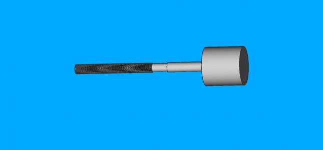
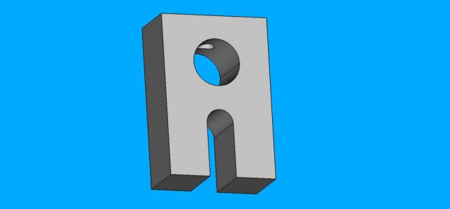
Still puttering along on FreeCAD 0.19 release. I have constructed a bracket, and a special screw that are to be parts of an assembly for my diamond dresser for my carbide grinder. I previously posted the main block about two pages back. Had a little fun with the pseudothread because the profile wasn't quite connected to the x-axis. Thought I had it constrained correctly, but apparently not. Had to redraw and reconstrain. Eventually I will get the hang of it.

Have a general question about assemblies. My screw is an integral part of the design. How does one model the screw so that basic 3D fit checks can be done? Does one then have two models of the screw? The fit check one, which the threads are converted to the minor diameter, and a "real one" that one can make a part from? The real one would have the major diameter on it, so I would know how to machine it. If there are two files, can I link them with a common spreadsheet? Trying to think of a way to make sure they are the same, in the ways that matter.

Kind of in a spot where I need to know what good practice would be. Might as well adopt it, rather than falling into yet another pit that I dug for myself!

Haven't modified the screw yet to put in the flange to retain the clamp. Didn't notice I left it out until just recently. The flange will be to the left of the knob, but to the right of the reduced shank. The design dimensions are in a spreadsheet, so it won't be that hard to modify. Here are some pictures to get an idea. The only thing that has final dimensions are the overall dimensions of the block, since I bought the cast iron, and the diameter of the diamond tool.
pseudothreadscrew_diamond_dresser.jpg
dresser_clamp_block.jpgdiamond_dresser_block.jpg
 
For threaded parts that fit together in A2plus, I use the fakes threads on the bolts/screws and I use a plain hole without threads set to the major diameter on the nut/female part.

I make a note on the drawing that it's threaded.
 
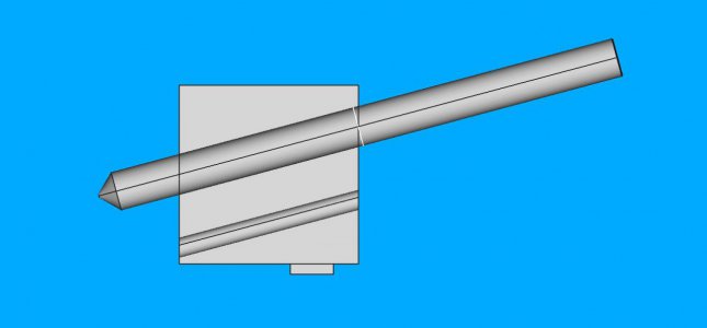
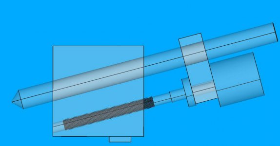
Have to mess around with this some more, (fix the screw) but have an assembly something like this:
first_dresser_assembly.jpg
Not quite sure how to get the tilted rectangular block face to the knob face yet. Nonetheless, I'm encouraged!
 
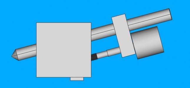
Little bit closer. Learned about making the planes adjacent. Fixed the screw to add a flange. Best of all, no interference. Only thing I can think of is to make a slit in the clamp block and put in a screw. Oh, yeah, maybe machine the main block face at an angle. That would probably blow up in my face, due to the topological issue. Maybe I'll copy all the files and try in a separate directory.
seethruassembly.jpg
 
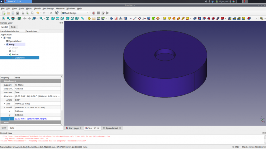
I have had problems due to the topological naming issue in the past, but have learned to avoid it for the most part. As noted the trick is to avoid sketching on faces of parts, bu rather reference them to one of the "origin" planes. The sketch attachment can then be offset if necessary, using the data fields for the sketch. Rather than put hard coded distances in those fields my preferred approach is to reference a FreeCAD spreadsheet. This can be used to define both the size of a pad (or other feature) and the offset for sketches that reference faces of that pad. This way chaging a dimension in the spreadsheet causes all the necessary dimensions to update simultaneously and avoids the problems associated with the naming issue. In the image below, the blue (22.00mm (spreadsheet.height) data in the Z field is drawn from the appropriate cell in the spreadsheet. The height of the pad forming the large cylinder is also drawn from the same cell, so the pocket will always be in the right place even if I change the height of the cylinder. I hope that makes sense and is helpful. For simple projects I sometimes don't bother with the spreadsheet, but for anything remotely complex, it is well worth the effort. Especially if your working out relationships as you go.

-Pete

Screenshot_2022-01-27_08-34-27.png
 
I have had problems due to the topological naming issue in the past, but have learned to avoid it for the most part. As noted the trick is to avoid sketching on faces of parts, bu rather reference them to one of the "origin" planes. The sketch attachment can then be offset if necessary, using the data fields for the sketch. Rather than put hard coded distances in those fields my preferred approach is to reference a FreeCAD spreadsheet. This can be used to define both the size of a pad (or other feature) and the offset for sketches that reference faces of that pad. This way chaging a dimension in the spreadsheet causes all the necessary dimensions to update simultaneously and avoids the problems associated with the naming issue. In the image below, the blue (22.00mm (spreadsheet.height) data in the Z field is drawn from the appropriate cell in the spreadsheet. The height of the pad forming the large cylinder is also drawn from the same cell, so the pocket will always be in the right place even if I change the height of the cylinder. I hope that makes sense and is helpful. For simple projects I sometimes don't bother with the spreadsheet, but for anything remotely complex, it is well worth the effort. Especially if your working out relationships as you go.

-Pete

View attachment 393973
I have been using spreadsheets for a lot of my design now. It is slower, but it is really nice when in an exploratory mode.

Is there a way to minimize the topological problem in assembly? Was using A2+ and didn't see a way to avoid using faces. Made a change on a part and the assembly got hosed (due to the topological renaming). Only way out of it that I could find was to remove the part and replace it. Really wanted to align to a plane, not the part, but didn't see any way to do it. Also don't see a way to resolve conflicts, since I don't see a way to highlight the issue. Hard to fix what you don't even know it is broken. But this is probably due to my inexperience.
 
I don't think there is a way to avoid the topological naming issue in A2+. At least I don't know of a way.

It's best to do the assembly at the end when parts are stable.

But, I've redone the assembly many times on some designs that I had to make modifications to.
 
Back
Top