FreeCad - really just getting started

For threads, I rarely make them correctly using a helix. The computations are really intense and FreeCAD slows down. Since I don't have a 3D printer, they don't need to be helixes.

I make them circular (round) and use the linear function to make as many threads as I need. They "look" correct, but really aren't.
Do you stack disks, or do the revolve a sawtooth sketch, out of curiosity? Stacking disks, looks easier, but too inexperienced to know.
 
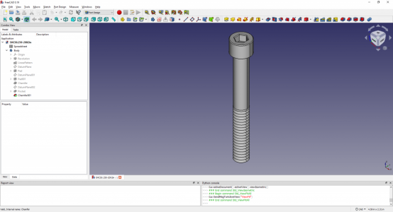
Yes, I stack the discs so I can make the fastener parametric. I created a library of fasteners of various sizes using a spreadsheet. Each has it's own file for use in A2plus.

There is a fasteners workbench in FreeCAD, but these fasteners act differently in A2plus, so I created my own.

I attached one for you. It's a SHCS 1/4-20 X 2". It should be easy to create any size you need by just changing the spreadsheet. I use boltdepot.com as a reference for creating these since they list all the needed dimensions.

1642413646298.png
 

Attachments

  • SHCS0.250-20X2in.FCStd
    76.9 KB · Views: 1
Seem to be having a little problem with tech draw. I had dimensioned the distance from the center of the hole to an edge, and also from center of the hole to the center of the next hole. When I changed a value in my spreadsheet, the tech drawing did a redraw as expected, but the dimension lines were no longer attached to the centers of the holes. So the dimension lines are not attached to the correct place any more. There doesn't seem to be a way to edit the dimensions, (you can change the format) only delete and start over. Is this correct? How can I dimension center of hole to something else?

I changed the parameter values in my spreadsheet, because I did a reality check on my mill table and found the tee-nuts would be really sloppy. Also found the middle slot is a bit narrower than the outer slots. So much so that the homemade tee-nut binds some. Measured a nut and found it was 12.04mm, should be just under 12mm. Whoops. This is what made me change the model. Thought I would be good, since the model was parameterized. Everything is good, save for the dimensioning issue in the first paragraph.
 

Attachments

  • techdraw_tee-nut_12mm_dimlines_moved.pdf
    219.7 KB · Views: 3
  • tee_nuts.FCStd
    1.6 MB · Views: 1
I'm taking a look at, but things look confusing because you used mm in the spreadsheet and I'm set for inches. Do you intend to use mm's?

You can enter imperial dimensions in the spreadsheet by adding "in" after the dimension.
 
I'm taking a look at, but things look confusing because you used mm in the spreadsheet and I'm set for inches. Do you intend to use mm's?

You can enter imperial dimensions in the spreadsheet by adding "in" after the dimension.
Thanks. At the moment, I'm set up for mm. Trying to follow the videos, which are in mm. Since the drawing is actually for a metric tee-slot, might be ok to mostly keep it metric. Thank you for the tip in dimensioning, I will try that.

I see in some FreeCAD docs that attaching dimensions can suffer from topological naming problem. This is discouraging. It's likely this is the root problem. There is a way to attach to the 3D model. For my tech drawing, I wasn't using an isometric view. Even so, I'd still like to dimension holes from center to center.

Topological naming IS the issue. Was not expecting to be bitten with this for such a simple drawing. Just by opening and closing the Body view, and rotating the model view, the tech drawing dimensions have moved. Now the dimension is from the left side of the part to the second to last hole. That's not what I originally drew. It's not what I dimensioned.

FreeCAD won't be acceptable until I learn how to totally avoid this, or the SW is changed. I hear the developers are working on the the change, but I'm not holding my breath. This is a simple drawing - yes, I can patch it. But I sure am not going to redo every dimension on a complex drawing, or groups of drawings. I thought I was creating the model ok, but apparently I have a lot to learn still. The topological issue greatly reduces the value of this software package to me. CAD should reduce workload, not increase it. Is there some good way, in general, to avoid this stupid dimensioning problem?
 
Last edited:
From what I understand, many CAD programs suffer from this issue.

There are a few YT videos out there on avoiding this issue. Basically, never sketch on the faces, use offset sketches or datum planes.

I've learned to live with it and deal with when it pops up. I can't see spending a lot of $$$ for Fusion 360 or other software when this is free and has absolutely no restrictions on use. YMMV.
 
I think I understand datum planes. Used them for my diamond dresser model. Didn't do that for the simpler tee-nut model, perhaps I should have. What is meant by an offset sketch?

Yesterday's comments came from me being frustrated with apparently random attachment of dimension lines. Was really afraid that complicated models would just become unmanageable. Must have posted at peak frustration! Sorry to have complained so loudly in public.

For CAD, my options are somewhat restricted, running on a linux platform. So can't use Fusion 360, free version or paid, or many of the other ones. Being retired, it doesn't make sense for me to "invest" in a CAD package, so I will plod along using FreeCAD. Nonetheless, still need to avoid minimize this topological problem. FreeCAD's documentation strongly suggests doing tech draw after being "finished". This just doesn't feel realistic, at least in my world. There's always revisions and changes. Like when one updates a drawing to as built. The better answer would be to come up with methods or software to minimize the topological problem so the tool always works. Apparently even a more proficient user such as yourself still has these issues occasionally.

At this point, just looking for guidance for good techniques to minimize the issue. Not sure how to fix the model I have. (It's good enough to machine a part from, since the drawing was corrected and exported it to pdf, freezing it.) Will experiment with the model to make it more resilient. Guess I will get rid of the helices, since they drive complexity and aren't necessary for visualization.
 
Maybe I used the wrong term, but an offset sketch is moved from its origin position. For instance, if you have a square 1" block and you want to put a hole on one face, you would pick a plane (such as XY) and use the position feature to move it 1" rather than sketch directly on the face.

Even when following this, I've seen some strange things happen in TechDraw when modifying the part. I just accept it and fix it.

I'm surprised that F360 is not offered on a Linux platform.

I would suggest removing the helixes from the part unless you are 3D printing it. Helixes are very complex computationally and will slow down FreeCAD considerably. If you look at the screw model I made, I just use circular rings to show where the threads are. Works fine.

Like I mentioned, I still struggle a bit with FreeCAD. But the more you use it, the better you get. I still have to search the web on occasion to do something.
Thanks for clarifying an offset sketch. I'll try that.

1 month ago, tried to download Fusion 360. Thought to myself, "hey, the big kids are doing that". Went there and found only Windows and MAC versions. I was disappointed, but not surprised. Most companies only want to support the major OS's. By volume of users, Linux just doesn't count, compared to Windows. Plus, Linux has variants (distributions) whose architecture varies. Multiple distributions makes it (slightly) harder to develop, simply from the configuration management perspective. I'm not making excuses for the software companies, but understand the commercial realities. But, it is no fun as a computer user to be left out in the cold.

FreeCAD isn't awful, but it does force the user to use a certain paradigm. It's taking me a while to adapt. From my limited perspective, the paradigm is awkward, but haven't been fully trained. Hopefully will be trained enough to blunder my way through what I need to do.

Will make a copy of the model and start playing from there. No point of buggering up the original file. Will remove the helix, and add pseudo-threads. I will try to modify the sketches to be less sensitive to faces. Thanks for the tips and the help, greatly appreciated.
 
Back
Top