FreeCad - really just getting started

For a beginner, his videos from about 13 on diminish in value and increase in confusion. Multi-parts assembly and Blender integration isn't what is needed right now. I do recommend his videos on the parametric electrical box and lid. That is good solid practice that results in something that is useful.
Thanks for the guidance. Could care less about blender. I do care about assembly. My first real project will have a couple of individual parts that need to be "assembled". Will check out the parametric electric box and lid. Kind of got a kick out of his parametric table design using a spreadsheet table.
 
For a beginner, his videos from about 13 on diminish in value and increase in confusion.
I completely agree. I stopped after Assembly 4, Assembly 3 seemed pointless. I also agree with @WobblyHand about needing to go back and scale to something close to the speaker's otherwise things get really turned around.

I actually made a part, after going through the series (up to 17). A simple open end wrench for the ER32 chuck I got for my lathe. My first attempt wasn't clean, but I got a design file out of it. I did a second design totally starting over and that was much cleaner. I ran into problems with points that weren't really connected, but still constrained. Trying to add a radiused fillet to an intersection of two trimmed arcs messed me up every time. I finally gave up, completed the sketch, padded it and THEN selected the resulting edge to apply a fillet. That worked and was clean and easy.
Exported to SVG (using Draft and Flattened SVG), imported into SheetCam, burnt it out of 11ga CR Steel on the plasma cutter and voila! A wrench!
 
Thought I could start to design something, that I thought was relatively simple. Apparently I haven't paid enough attention in class! :(

I made a part that is a solid block made from a pad and a second pad along the bottom. It seems ok. However, I'm not sure if the best strategy is to additively synthesize the solid, or subtractively do so.

I'd like to create a datum plane that aligns with one of the faces of the solid block in the XZ plane. Then I want to offset its origin to a location on (not really on, but I hope you understand) the face and then rotate the plane around the X axis. Then I could draw a circle in the sketch and pad it through the solid block at an angle. Based on my admittedly feeble comprehension of the videos, I thought this was a reasonable way to proceed.

Here's the part that is baffling me. I have a datum plane in XZ plane. I offset it so it would be on the rear face of the body. To do so I had to add z offset, which I totally don't understand. I thought it would be y offset? Can someone explain this? Have enough problems in normal geometry, seemingly changing the axes to something else is baffling. If I change the angle it appears to be rotating around the y axis. I'd like the rotation point to be around the x axis at a certain z offset. Clearly, I'm confused about this. Can anyone point me in the right direction? I'd greatly appreciate it.

I need to learn how to fish, not to have a fish, if you know what I mean.
 

Attachments

  • diamond_dresser.FCStd
    18.5 KB · Views: 1
Here's the part that is baffling me. I have a datum plane in XZ plane. I offset it so it would be on the rear face of the body. To do so I had to add z offset, which I totally don't understand. I thought it would be y offset? Can someone explain this? Have enough problems in normal geometry, seemingly changing the axes to something else is baffling. If I change the angle it appears to be rotating around the y axis. I'd like the rotation point to be around the x axis at a certain z offset. Clearly, I'm confused about this. Can anyone point me in the right direction? I'd greatly appreciate it.

I've noticed this, too. I think the way it works is that the offset is relative to the datum plane. I think I always use the Z offset.
 
Edit, I misunderstood the question
 
Last edited:
I've noticed this, too. I think the way it works is that the offset is relative to the datum plane. I think I always use the Z offset.
Ah, it is a feature ;) Thought I was going insane. In the absolute reference, it is a y offset. So you are saying it a local right hand coordinate system? How do I know which side of the plane is the right one?
Your datum plane is in the XZ plane. It in theory extends out to infinity in the X and the Z directions. Thus to move it front-back, you need to offset it on the Y-axis.
Well, that's what I thought, but offsetting the attachment offset position in the y direction appears to do nothing. Only the z dimension seems to work, which appears to be consistent with a local reference. So up is +y, right is +x, z would be movement in the absolute y axis.

:applause 2: This seems to work. Made a 15 degree 7/16" diameter hole through the body! Just what I wanted. Wow, slow sledding, but at least some progress. Offset the y axis for the hole position, and the z axis to line up with the body face. Then changed the angle axis to z so the plane would rotate into the block. Whew. Made a pocket through all and symmetric to plane and done with that bit. What a learning curve!
 
Last edited:
That's why I removed the comment. I'm at work at the moment... internet puzzlements get fitted between calls.
 
I have found a nugget on reddit:

"Don't be confused, this z-direction is local to the datum plane itself. So you are moving along the perpendicular of the plane."
 
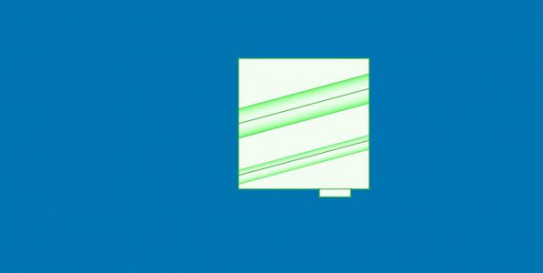
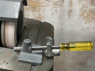
Trying to make something approximating this:
1642191722712.png
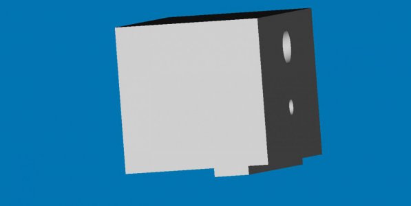
So far my part looks like this:
block_progress.jpg
Having trouble showing the pockets which enter on the right and go down 15 degrees to the opposite face. Sometimes I can get them to show, through the body and other times not.

Edit: finally was able to get this:
view_with_internal_details.jpg
Don't know what the secret is. :( Seems random.
 
Last edited:
Back
Top