FreeCad - really just getting started

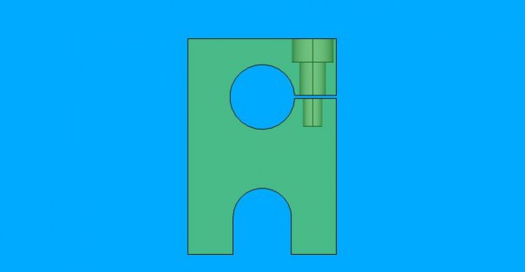
Decided to not have a thumb set screw in the clamp block. Rather, would like to cut a slit in the block and then use a screw to clamp the slot.
How can one do a slit?

Edit: Nevermind, figured it out. Made a sketch and did a pocket to first face. Hmm, this is getting a little easier!
 
Last edited:
In Part Design is there a way to see inside the part? I know in A2plus one can make the part transparent. I made the slit then added a tap sized screw hole and counterbore for the clamp. Made another pocket for the clearance. It's hard at this point to make sure I did it right. It there some way to view variable slices through the part? Haven't found that. But did find some Appearance options. Seems my clearance hole went through the slit, and I didn't want that. Think I fixed it.
seethruclampblock.jpg
Wow. So cool.
 
In Part Design is there a way to see inside the part? I know in A2plus one can make the part transparent. I made the slit then added a tap sized screw hole and counterbore for the clamp. Made another pocket for the clearance. It's hard at this point to make sure I did it right. It there some way to view variable slices through the part? Haven't found that. But did find some Appearance options. Seems my clearance hole went through the slit, and I didn't want that. Think I fixed it.
View attachment 394560
Wow. So cool.
Yes, you can make parts transparent in parts design. Right click on the body in the left side model tree, Appearance on the menu, transparency slider near the bottom of the menu that pulls up on the left.

Techdraw lets you do section cuts.
 
Yes, you can make parts transparent in parts design. Right click on the body in the left side model tree, Appearance on the menu, transparency slider near the bottom of the menu that pulls up on the left.

Techdraw lets you do section cuts.

Slowly getting there. Extremely slowly. Section view isn't intuitive to me. Was getting inscrutable errors just clicking the icon. Had no idea what the error was, since it used software variable names, instead of telling me what to do. Hmm, one has to select a View in the Tech Drawing! Must of missed that in the docs... Even with this discovery, section stuff is an enigma to me.

The coordinate system for section view is not obvious. Had to move them all around to find something to move. But think I have something ok.
One thing I did find, is the Section View plane coordinate will not allow an entry from the main drawing's spreadsheet. That stinks. I had to manually enter the coordinate. Simply did not recognize me typing Spreadsheet. like it does in Part Design.

But this is what I have so far for the Clamp Block Tech Drawing. It isn't as readable as I would like, but think it is serviceable. I'll find out in a bit, since I will make a physical part from it.
 

Attachments

  • techdraw_dresser_block.pdf
    203.7 KB · Views: 4
You're getting there it seems. The coordinate system drives me crazy too, I end up doing the same thing for most things. I just change values until it moves in the direction I want. Not optimal ... but it works.
Your drawing looks good!
 
Last edited:
Trying to use the Fastener workbench. In particular, for a (different) design I want to use a shoulder bolt. I can select an ANSI shoulder bolt, but it seems that one cannot independently control the shoulder width and the thread width. I'd like to use a 1/4" diameter shoulder bolt that has a 5/8" long shoulder and 1/4-20 threads. McMaster sells these bolts. FreeCAD Fastener Workbench apparently doesn't acknowledge this kind of shoulder bolt. If I select the 1/4" shoulder bolts, it gives me a shoulder that is significantly wider than 1/4".

After playing around, it seems it sizes the bolt by the thread size. So a 1/4" diameter shoulder bolt uses a #10 screw. These bolts are a lot cheaper than the ones above. $1.44 vs $5.22. How one places the bolts is curious. Negative offset installs the bolt. One needs to select the edge of the hole to locate the screw. First time I tried, the bolt was inside a body!

What is the purpose of this workbench? Is it for checking clearance? Does one use this only in assembly? Or not even there?
 
I started using the fastener workbench, but didn't like how they were used in A2+. They aren't treated like normal bodies/parts. Plus, I like controlling every dimension. That's why I created my own fasteners using spreadsheets.
 
I started using the fastener workbench, but didn't like how they were used in A2+. They aren't treated like normal bodies/parts. Plus, I like controlling every dimension. That's why I created my own fasteners using spreadsheets.
I didn't understand how fasteners were used in A2+ at all. I ended up placing the fasteners into individual parts, primarily looking at clearance for pivoting parts. I still find A2+ a PIA since it breaks nearly every time one makes a change in a part. Can't wait for a better solution to the topological naming problem. Of course it would be better if I was a better designer, or even if I had thought out the design fully before entering it in CAD, but that's how it is right now.

Another grumble about the Fastener Workbench is there are no UNF or UNS threads available, only UNC.
 
Last edited:
Speaking of assembly, (A2+) what is the correct way to constrain a lever to a pivot, so that one can rotate the lever about the pivot? I did it once, (by accident, in a different design,) but can't remember how. Now the lever is immovable in assembly. It should be able to swing about the pivot. Guess it is over constrained.

What I have is: planesParallel, axisParallel and axisCoincident. I think rotation wouldn't violate those constraints.
axisCoincident allows movement coaxial to the pivot, but not rotation. I want the lever to stay in the slot and rotate around the pivot.

Found a post dated January 2021, claiming rotation is only done by the solver and not via the mouse. Mouse can only do translation. Work around is to add a dummy object and move it. Haven't tried it yet, don't understand it, and it seems like a hack. A2+ rotation? Would I add a dummy sphere to the lever? Why is moving the sphere constrained to the lever different than moving the lever?
 

Attachments

  • cutter_assembly.FCStd
    47.2 KB · Views: 1
I can't help with animation. I've never done it.
 
Back
Top