-
Welcome back Guest! Did you know you can mentor other members here at H-M? If not, please check out our Relaunch of Hobby Machinist Mentoring Program!
You are using an out of date browser. It may not display this or other websites correctly.
You should upgrade or use an alternative browser.
You should upgrade or use an alternative browser.
G0704 CNC Conversion (yes, another thread on this :) )
- Thread starter wachuko
- Start date
- Joined
- Aug 6, 2015
- Messages
- 3,886
Last edited:
- Joined
- Aug 6, 2015
- Messages
- 3,886
- Joined
- Mar 26, 2018
- Messages
- 2,724
Allright, sorry for taking so long to get back to you @wachuko.
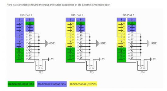
The trick with this is that all the port 3 DEDICATED INPUT PINS (Port 3 Pins 10, 11, 12, 13, 15) are pulled HIGH to 5V by the board. These require external PULLDOWN resistors since we are applying 5V to the pin through the pendant.
You can use a range of values for the resistor, but choose something between 200 ohm and maybe 2000 ohm? An external 4.7kohm resistor might be too weak to pull the input down. I chose 220 ohm and they work great, but the exact value is not super important.
Read the note here about the input pins from Warp9 TD
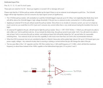
As for the pin numbering, read the following:
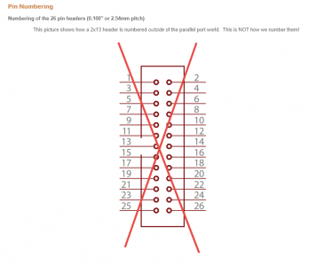
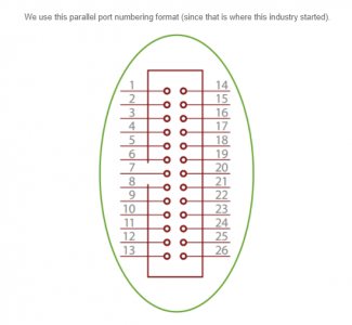
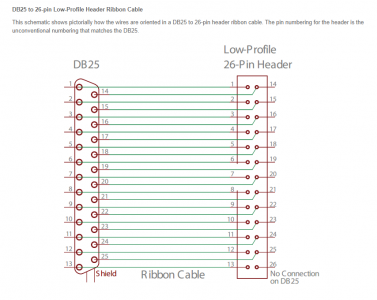
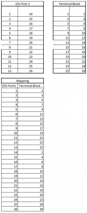
I personally don't like this, but I understand why they did it. Since the IDC-26 breakout board follows the IDC-26 pinout, the numbers will be wrong for the smoothstepper. A piece of masking tape and a fine point sharpie will help you renumber the board.
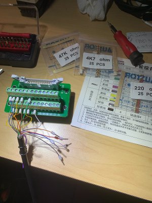
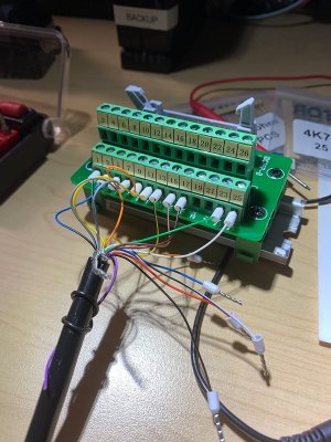
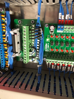
Take a look at my installed board. The black devices jumpering between pins are the external pulldown resistors. There are 5 of them. Terminal 1 starts on the bottom row, bottom of the image and counts upwards to pin 13 on the bottom row, top of image. Then the numbering starts again at 14 on the top row, bottom of image, and finishes up at pin 26 on the top row, top of image.
You may prefer to source 5V to the pendant directly from the ESS using pin 26. If you do this, you need to make sure JP4 is installed on the ESS. The risk is that a short outside the cabinet in the pendant will drop out the ESS and potentially damage it. For this reason I externally sourced 5V.
Let me know if this clears things up a bit more.
Mike
EDIT: all of this info is presented here: https://warp9td.com/index.php/documentation/doc-ess#TechnicalDetails
The trick with this is that all the port 3 DEDICATED INPUT PINS (Port 3 Pins 10, 11, 12, 13, 15) are pulled HIGH to 5V by the board. These require external PULLDOWN resistors since we are applying 5V to the pin through the pendant.
You can use a range of values for the resistor, but choose something between 200 ohm and maybe 2000 ohm? An external 4.7kohm resistor might be too weak to pull the input down. I chose 220 ohm and they work great, but the exact value is not super important.
Read the note here about the input pins from Warp9 TD

As for the pin numbering, read the following:


I personally don't like this, but I understand why they did it. Since the IDC-26 breakout board follows the IDC-26 pinout, the numbers will be wrong for the smoothstepper. A piece of masking tape and a fine point sharpie will help you renumber the board.
Take a look at my installed board. The black devices jumpering between pins are the external pulldown resistors. There are 5 of them. Terminal 1 starts on the bottom row, bottom of the image and counts upwards to pin 13 on the bottom row, top of image. Then the numbering starts again at 14 on the top row, bottom of image, and finishes up at pin 26 on the top row, top of image.

You may prefer to source 5V to the pendant directly from the ESS using pin 26. If you do this, you need to make sure JP4 is installed on the ESS. The risk is that a short outside the cabinet in the pendant will drop out the ESS and potentially damage it. For this reason I externally sourced 5V.
Let me know if this clears things up a bit more.
Mike
EDIT: all of this info is presented here: https://warp9td.com/index.php/documentation/doc-ess#TechnicalDetails
- Joined
- Aug 6, 2015
- Messages
- 3,886
No worries, I am just happy to get the help figuring this out.
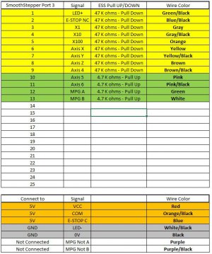
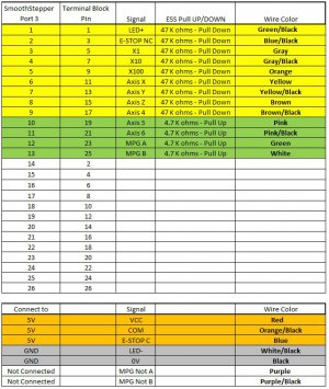
Okay. So that means that the mapping of the pins I did is now correct. Easier for me to have the mapping on a spreadsheet. Maybe later I can replaced the label on the terminal block for matching the numbering of the ESS... spreadsheet will do for now.
As you did, I will source the 5V from the same power supply that feeds the ESS board. I will not do it via the ESS board and pin 26.
I am also following your recommendation and using 220 ohms resistors.
But the question that I still not able to answer is: Where do I install the resistors? I see them on your board... but what are these connected To/From - The "From" I get, it is the "To" that I do not see... That is where I am confused.
You have one resistor going from 4 to 12
And the other going to 18, 20, 22, 24
Is this because that means you are placing the resistor between the GND on the ESS board and the Pendant wires? So I can basically do that with mine... any ESS pins between 18-25 (corresponding Terminal Block pins 10,12,14,16,18,20,22,24) is fine?
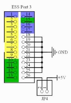
Also, why only 5 resistors? X, Y, Z and ?? MPG A and MPG B?
Okay. So that means that the mapping of the pins I did is now correct. Easier for me to have the mapping on a spreadsheet. Maybe later I can replaced the label on the terminal block for matching the numbering of the ESS... spreadsheet will do for now.
As you did, I will source the 5V from the same power supply that feeds the ESS board. I will not do it via the ESS board and pin 26.
I am also following your recommendation and using 220 ohms resistors.
But the question that I still not able to answer is: Where do I install the resistors? I see them on your board... but what are these connected To/From - The "From" I get, it is the "To" that I do not see... That is where I am confused.
You have one resistor going from 4 to 12
And the other going to 18, 20, 22, 24
Is this because that means you are placing the resistor between the GND on the ESS board and the Pendant wires? So I can basically do that with mine... any ESS pins between 18-25 (corresponding Terminal Block pins 10,12,14,16,18,20,22,24) is fine?

Also, why only 5 resistors? X, Y, Z and ?? MPG A and MPG B?
- Joined
- Mar 26, 2018
- Messages
- 2,724
Ah shoot left out that info...No worries, I am just happy to get the help figuring this out.
Okay. So that means that the mapping of the pins I did is now correct. Easier for me to have the mapping on a spreadsheet. Maybe later I can replaced the label on the terminal block for matching the numbering of the ESS... spreadsheet will do for now.
As you did, I will source the 5V from the same power supply that feeds the ESS board. I will not do it via the ESS board and pin 26.
I am also following your recommendation and using 220 ohms resistors.
But the question that I still not able to answer is: Where do I install the resistors? I see them on your board... but what are these connected To/From - The "From" I get, it is the "To" that I do not see... That is where I am confused.
You have one resistor going from 4 to 12
And the other going to 18, 20, 22, 24
Is this because that means you are placing the resistor between the GND on the ESS board and the Pendant wires? So I can basically do that with mine... any ESS pins between 18-25 (corresponding Terminal Block pins 10,12,14,16,18,20,22,24) is fine?
View attachment 376715
Also, why only 5 resistors? X, Y, Z and ?? MPG A and MPG B?
The "To" is any available GND. This could be any terminal 18-25. Whichever is convenient from a location standpoint.
You only need resistors for the GREEN dedicated inputs. Bidirectional inputs (YELLOW) have pulldown resistor already and don't need anything external.
- Joined
- Mar 26, 2018
- Messages
- 2,724
Let me know! Should work well for you.Got it!! Driving back home tonight. Will give this a go tomorrow!!! Can't wait to test it out.
Thank you!
- Joined
- Aug 6, 2015
- Messages
- 3,886
IT WORKS!!!! The MPG Pendant is finally working!! E-Stop on the MPG Pendant is also functional!


Thank you @macardoso !!!


Thank you @macardoso !!!
Last edited:


