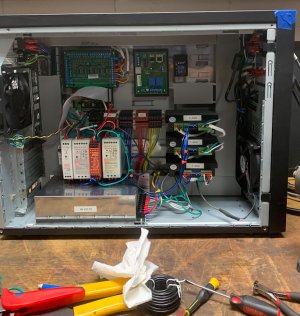
G0704 CNC Conversion (yes, another thread on this :) )

That's very clean and organized. I can't wait to have funds to convert mine. Following yours closely. Thanks!

Thank you for the kind words. All the credit for the organization goes to @macardoso for the encouragement and coaching he has provided during all this build... All the crappy stuff, well, that is all me! :p

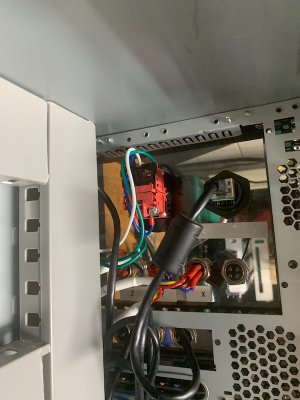
Some good news... found the other half of the emergency stop. Looks like I had started to wire it.

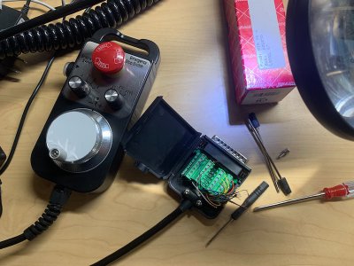
And also meditating and calling upon the gods of CNC to help me getting into the right state of mind to tackle the wiring for the pendant... I am really, really dreading that task...
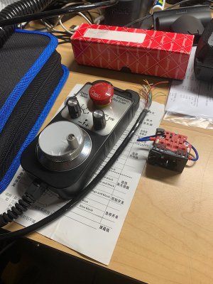
IMG_1447.jpeg

Looking at other conversions, looks like this shield has to go along with the safety switch. I did not wanted to cut any wires at this time, so just took a blade and got the two wires connected to each other. Some heat shrink on them and tucked it away from any spinning parts.
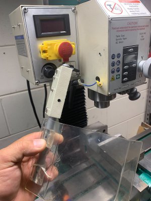
IMG_1444.jpeg

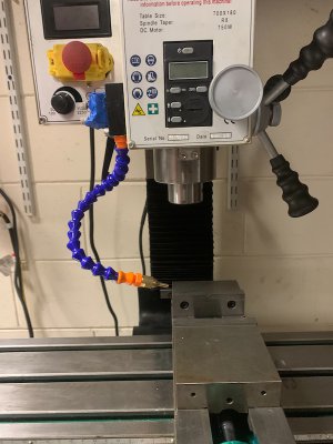
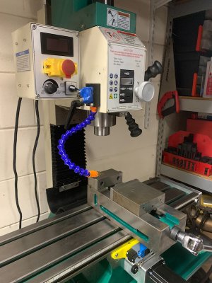
The next, I must admit, is what a typical poser will do... I am so far from doing any cooling... but I had to install this just for encouragement. No, stop it Wachuko! Okay, okay... I did it just for the photo, buaaahahahhahahaa
IMG_1446.jpeg

IMG_1445.jpeg
 
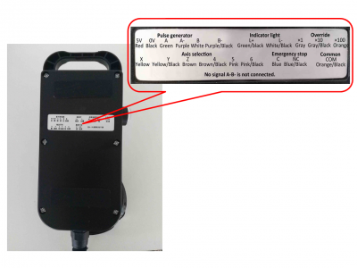
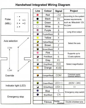
Found translated photos for the wiring of the pendant.

Placing here for future reference:

MPG_handheld_hand_wheel_13.png
MPG_handheld_hand_wheel_14.jpeg


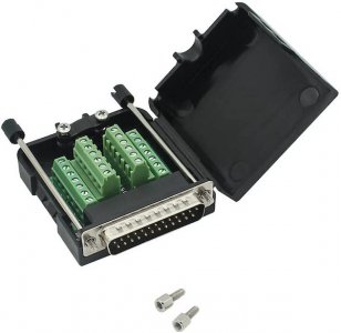
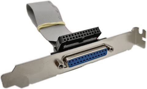
And had to order a DB25 connector... looks like I never order one...

DB25 Connector.jpg

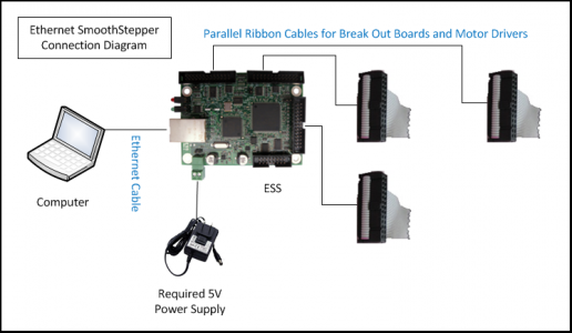
I should be able to connect the ribbon cable I had to the Warp9 Ethernet Smooth Stepper (ESS) board.

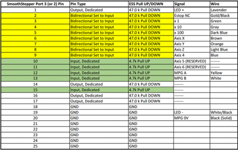
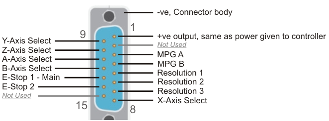
Wiring diagram from Warp9 and link to the setup I need to do in Mach4

Pendant01WiringChart.png

ESS Basic Connection 2.png

And the MPG Pendant will connect in the back of the case to this... cool...

DB25 ribbon cable.jpg

So it should not be that complicated... fingers crossed.
 

Attachments

  • MPG-Connections.png
    MPG-Connections.png
    50.9 KB · Views: 55
Last edited:
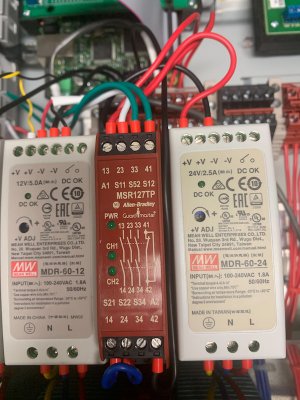
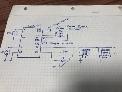
Additional information to remember for the wiring of the E-STOP

1584363997554-png.316901


  • 24V to A1
  • DC COM to A2
  • Jumper S21 to S22
  • S11 to one side of your ESTOP (jumper to both N.C. contacts if you have 2)
  • One ESTOP N.C. contact to S52
  • One ESTOP N.C. contact to S12
  • 5V to terminal 13
  • Terminal 14 to ESS ESTOP input pin.
  • DC common to terminal 23
  • Terminal 24 to Stepper Drive Enable
Make sure that your V- from all 3 power supplies are tied together (this is very important). This wiring will give you simultaneous ESTOP channels, one killing the steppers and one telling Mach 4 that the steppers have been shut down.

You have one more Safety channel (33 & 34) that can be used to power down a device (like a spindle) and one Aux channel (41 & 42) that is N.O. and can be used for diagnostics like a lamp that is ON when the ESTOP is pressed in.
 
Last edited:
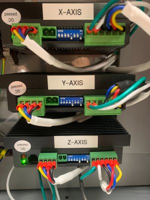
Okay... went back to play with the dip switches on the drivers to see why it was going so slow... Turns out, I had them set incorrectly.

IMG_1451.jpeg

I moved them all (SW5-8) to ON. This is supposed to allow for the software to control it.

IMG_1452.jpeg

All working fine now. Another mistake corrected.

Dip Switches.jpg

 
Last edited:
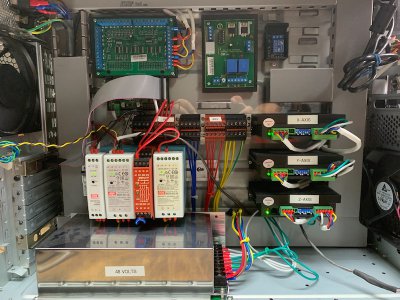
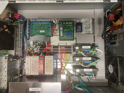
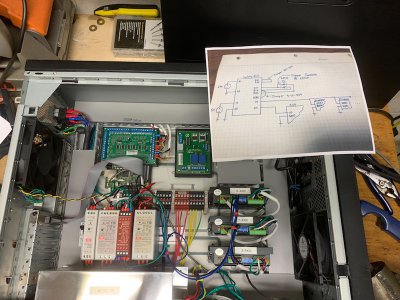
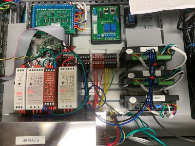
Wiring the E-STOP...

IMG_1459.jpeg

IMG_1456.jpeg

Still need to confirm if the wire that goes to the ENA on the stepper drives needs to be jumped to all ENA+ pins on the stepper drives or to just one... And then, I think that there is software changes I need to make to enable the E-STOP function.

Oh, and just noticed I forgot to install back the cover on the left wire organizer...

DB25 ribbon cable to parallel port installed as well. That is where the MPG Pendant will connect to...

IMG_1458.jpeg
 
Okay... MPG A is yellow and goes to 12... oh no, wait... that is not the correct color... so Green is MPG A and goes to 3 and... and what is this Orange/Black COM, where does that goes??? arghhhhh....

IMG_1462.jpeg
 
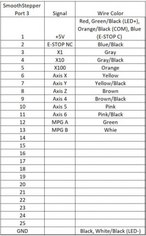
I was getting confused with the Pendant wiring... made a table for the mapping as I understand it, from reading that link I posted from warp9td.com

MPG Pendant Wiring.JPG

And the wires not used:

Purple: MPG A- (or also called Not A )
Purple/Black: MPG B- (or also called Not B )

Will wire it that way and test next week... Looks like I will be doing hard labor in the yard this weekend...
 
I am still not wiring the Pendant correctly... so many mistakes...

Pin 1 goes to Green/Black (LED +) that is the only wire that goes there...

These wires DO NOT go to the SmoothStepper Input pins: Red (MPG VCC), Blue (E-STOP C), Orange/Black (COM) - these need to be connected to 5V.

So now I need to see how I can feed 5 volts to those wires with the current setup. I think that I will need a bridge of some sort to be able to still connect to the DB25 plug in the back and then, inside the box, with a punch out block (??Name??) map those wires to 5volts while the rest go to the SmoothStepper board...

And the E-Stop is not working as it should. So I unplugged the two wires that go to each driver (ENA+, ENA-), to get the system working again. Will sort that out later.
 
Took a break to practice indicating the vise... I have to do this all over when I am done with the conversion, but being that I have never done it... and after watching all those videos... I had to give it a try...


Now I can finish packing for my trip, lol.... really, Iook! squirrel!! I get distracted so easily...
 
Back
Top