- Joined
- Jun 12, 2023
- Messages
- 41
Good morning all
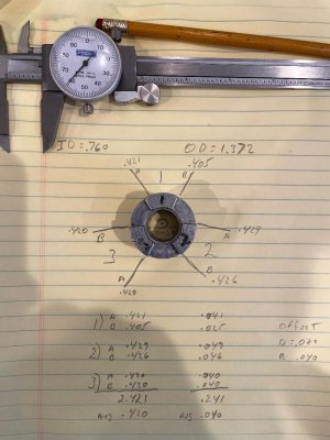
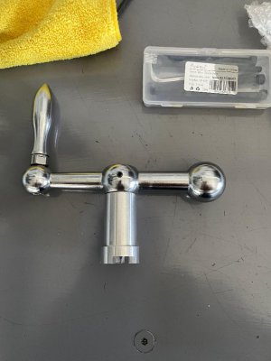
extropic; I believe this is what you requested, please let me know if I didn't fulfill your directions completely. My original ID measurement was off .005" the correct ID=.760" The off set for this exercise looks to be R=.040". See picture. I average all so I could give a clean measurement. Raw data is included.
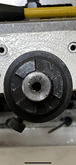
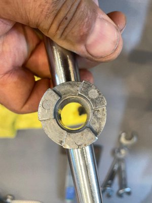
Just for fun; this is a shot of the machine hub, I didn't remove it because I don't have a new roll pin if I mess it up at this time, sorry.
Thank you
extropic; I believe this is what you requested, please let me know if I didn't fulfill your directions completely. My original ID measurement was off .005" the correct ID=.760" The off set for this exercise looks to be R=.040". See picture. I average all so I could give a clean measurement. Raw data is included.
Just for fun; this is a shot of the machine hub, I didn't remove it because I don't have a new roll pin if I mess it up at this time, sorry.
Thank you