Mike's CNC G0704 - Block 4 Upgrades

Can you explain this, please?
Yeah I guess I glossed over that. There’s quite a few scraping videos that will explain it far better than I can in writing but I’ll try my best.

Hinging (or hingeing, Merriam Webster had both spellings) is a scraping test method that helps a scraper identify surface flatness. Marking with blue is surprisingly not helpful at identifying some forms of global curvature on a part. More definitive tests are required to help a scraper be confident they understand the surface condition and take passes accordingly.

Take this as an example: a square surface is bowed outward (convex) in the middle by a thou or two in a spherical shape. An inexperienced scraper could mark this against a flat surface plate and generate a surface consistently marking all over indicating a surface true and flat as good as their surface plate. However the true surface is far from flat.

This is where hinging is applied. You grab one side or corner and apply side to side motion (trying to only introduce a rotation and no rocking motion) and observe where the part hinges or pivots about. A truly flat surface with consistent and even bearing will hinge at the centerline of the part roughly 1/3 of the distance across the part measured from the opposite edge from which you are applying the force. If the part is not flat, then the part will hinge on the highest area (globally speaking). The part must be hinged from both sides in case the global high point happens to be at the 1/3 location on one side.

Going back to our example, this convex plate will hinge in the dead center and the scraper will know that even though the blue markings are indicating flatness all over, they lie about the true surface condition.

A concave surface might hinge properly, but will not blue over the full surface.

A long skinny workpiece like a straightedge will hinge at the far ends (like mine) if it is bowed concave.

And a twisted workpiece will hinge at opposite corners rather than the centerline of the part.

A scraper needs to use a combination of bluing, hinging, rocking (tipping to part to feel or listen for twist), tapping (hitting corners with a small weight to listen for hollowness), and indicator measurements to determine the true surface condition.

But again, I’m not an expert, so take my understanding with a grain of salt.

This process also makes a lot more sense when you watch it done. I’ll try to find some good YouTube clips when I have time.

Edit: there are some techniques to rubbing the part against the surface plate coated in marking medium that reduce the risk of accidentally marking a bowed surface inaccurately. Specifically, MTR recommends applying lateral force to the part (or straightedge) from one end only and leaving the other completely unsupported. There should be no downward pressure into the plate other than the effects of gravity. All of this is to prevent rocking or rolling a curved part against the plate.

Another point is that the surface should mark consistently time after time (often called stabilized). If you take repeat markings with blue and each reads differently, it is likely that your part is rocking on the surface.

Rectifying this situation can actually be a bit tricky. It may require you to blindly scrape a few passes where you think the curvature is, or you might need to apply a very thin shim on one corner of the part during bluing (especially on twisted parts) to create a 3 point kinematic mount and start scraping from there until the twist is gone and the markings stabilize.
 
Last edited:
Thank you for that explanation.
I remember learning about grinding mirror blanks. The technique was to use three blanks ground against each other, since using only two could result in one becoming convex and the other becoming concave. With three, that’s not possible.
 
I don't really understand the idea behind your column reinforcements. If the channel is not mechanically (through bolting or epoxying) coupled to the column, then it isn't going to do anything to increase the stiffness of the column. It may help with vibration damping I guess, but it's a lot of work and money just to do that. I'm not sure why you're worried about stresses or movement that bolting the channel to the column might introduce, after all you're going to all this effort to scrape everything into the correct geometry anyway.
 
Thank you for that explanation.
I remember learning about grinding mirror blanks. The technique was to use three blanks ground against each other, since using only two could result in one becoming convex and the other becoming concave. With three, that’s not possible.
That would be referred to as the "three plate method" and it is somewhat frequently discussed on this site. It is a proper way to develop a truly flat surface from nothing, however is fairly impractical unless no other options exist. For scraping, the cost of a high quality surface plate is fairly insubstantial so the goal of scraping is to transfer the flatness of this "master surface" to the workpiece.
 
Last edited:
I don't really understand the idea behind your column reinforcements. If the channel is not mechanically (through bolting or epoxying) coupled to the column, then it isn't going to do anything to increase the stiffness of the column. It may help with vibration damping I guess, but it's a lot of work and money just to do that. I'm not sure why you're worried about stresses or movement that bolting the channel to the column might introduce, after all you're going to all this effort to scrape everything into the correct geometry anyway.

You might be very correct - it is something I've been pondering.

My initial concept was to bolt from all sides into the column and then backfill with concrete for vibration damping (probably as you are suggesting). My concern was that the MC channel is nearly as substantial as the column, so bolting could easily deform the column to match the shape of the MC channel (or some average shape of the two). Since scraping is so laborious, I thought that the risk of deforming the precision surfaces too far out of flat (even 2 thou could take a LOT of work to correct, 20 thou would be impractical) outweighed the rigidity gains. Furthermore I was concerned that introducing stresses into the structure would cause continued movement of the composite structure over time and degrade any accuracy gains I made during scraping. I suppose that if I could somehow measure the exact standoff height to go between the channel and column at each bolting location, and I was careful to equally torque each bolt to the same value, approaching slowly and alternating tightening all over the column, perhaps I could reduce the stresses and deformation to a reasonable level.

My newer concept (not depicted well in the CAD) would be to have socket head cap screws bolted on the inside of the MC channel and the outside of the column (SHCS cap height ~3/8" and gap is roughly 1/2"). They would be arranged so the heads would alternate between being in the column or in the channel (but not touching). Concrete would then pour into this space and cure (ideally use expanding grout to tension the system). The channel would be rigidly bolted down the back of the column (potentially introducing a bow to the column, but not a twist). My thinking is that the cured concrete would transfer stress from the actual machine column, through the column mounted "stud", through the concrete, through the channel mounted "stud", and finally through the channel. I was hoping it would be nearly as rigid as a bolted connection, but with the added benefit of not introducing stresses to the structure which would act to deform the precision way surfaces and keep them as close to true as possible before scraping.

The success of my concept hinges on: the grout or concrete will not shrink during curing, the concrete "wets" the surfaces with some level of adhesion (rather than creating a loose separate component sandwiched between the channel and column, and that vibrations and stresses transfer well from the inner studs, through the concrete, and to the outer studs. Epoxy granite fill would help on many of these points, but the cost is hard to justify.

Bolting does remain an option that I am open to. Wish I knew enough about FEA to do simulations similar to @vinnito1; those were very impressive.
 
I think you can address all your concerns about introducing movement into the column by either using shims or jack screws. Then you can bolt up the two and see how it moves on your surface plate, adjusting the shims or jack screws to result in no net movement.

One benefit of using jack screws would be the ability to tweak the column if it pulls out of alignment in the future. To that end I'd suggest filling the gap with sand and lead shot. That will give you some added mass but allow you to adjust the column in the future if needed.
 
Cost analysis of Epoxy Granite for Column Fill

Estimated Fill volume: 152 in^2 + 25% = 190 in^3 or 105 fl-oz

Estimated Fill Mass: 13.2 lbs or 5.98kg

Estimated Epoxy Granite Density: 2400 kg/m^3 o

Target Recipe (rough estimate) by weight:
50% coarse aggregate (washed and dry small gravel), <0.1" diameter
20% medium aggregate (play sand)
15% fine aggregate (120 grit aluminum oxide powder)
15% Epoxy

Based on this, I estimate I'll need:
  • 32 fl-oz West Systems 105 & 206 epoxy kit $103
  • 6.6lb #10 screenings $40 if I can find it
  • 2.7lb play sand On Hand
  • 2lb 120 Grit Aluminum Oxide $21
Total cost ~$160, will make about double what I would need to fill the column, but can't buy smaller quantities.
 
I think you can address all your concerns about introducing movement into the column by either using shims or jack screws. Then you can bolt up the two and see how it moves on your surface plate, adjusting the shims or jack screws to result in no net movement.

One benefit of using jack screws would be the ability to tweak the column if it pulls out of alignment in the future. To that end I'd suggest filling the gap with sand and lead shot. That will give you some added mass but allow you to adjust the column in the future if needed.
Not a bad idea. Although, relying on dozens of jack screw pairs for precision alignment and trusting all of them not to come loose over many years sounds like a big risk. If the tension even just shifted, the alignment of the column would go out of whack.

If I were to bolt all around the column, I think I'd rather use standoffs and deal with whatever movement they cause.
 
The jack screws will all be under compression and even then, you can use loctite or locking nuts. I don't see the need for dozens of attachment screws - four for each of the three sides and one jack screw for each of those.
 
Took some time to update my old CAD models to reflect the current machine and all the planned new additions. I had so much junk in the old CAD directory that I decided to completely start from scratch, copying over only the parts I needed and building up a new assembly.

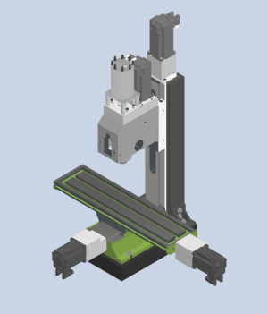
Here is the machine more or less as it stands today. Included are the planned column reinforcement, 4th stage to the pneumatic drawbar cylinder, revised 10,000 rpm spindle design, and granite surface plate machine base.

Missing so far is: limit switches, new ballscrews, ballnut mounts, Work holding models, Column reinforcement bolts and standoffs, new shaft couplings, gibs and screws, etc.

1689280189490.png

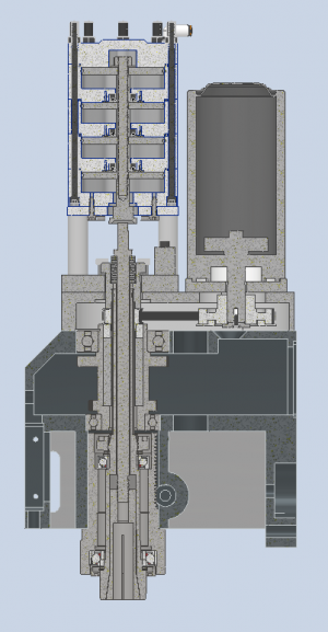
The spindle cross section is one of my favorite things to look at:

1689280950342.png

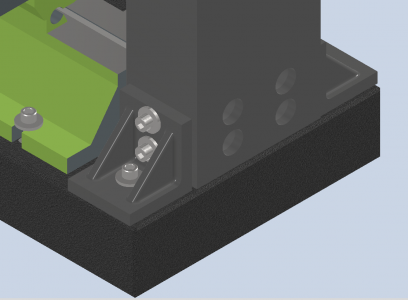
I've more formalized the column to surface plate mounting structure. Some KBC brand 3x3x3 ground angle plates will create the structure to resist deformation in the X direction and help support the Y as well. They're the simplest and cheapest option I could come up with that adds the most bulk to that connection. There are (2) 3/8-16 bolts into the column and (1) into the granite.

1689281139378.png

I considered some expanding threaded anchors for the granite over my epoxy concept, however I'm concerned about the radial force cracking or deforming the granite, especially since the holes are near the edges. If the glue in threaded inserts fail, then I can simply install these instead.

1689281245121.png 1689281254158.png

I need to revisit the belleville washer arrangement for the spindle drawbar tension. My current air cylinder can develop 1800 lbf of thrust at 90 psi (air compressor minimum) and the new design should offer over 2400 lbf.

The actual tension in the drawbar ends up much less than this amount as the cylinder needs to remove tension from the drawbar and compress the spring stack far enough to release the tool. So the working tension is potentially as little as half this amount. This can cause tool slipage in high vibration cuts. I haven't really had significant issues with this, but I would feel better with this improved. The tension is set my continuing to tighten the drawbar with a wrench until the tool does not release at minimum psi, then backing off slightly until it does. There is a slight amount of diameter variation in my tool holders (0.7491-.7498) that might also affect the spindle clamp force.

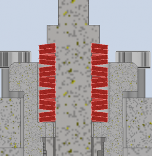
The current arrangement looks like (())(())(())(( which is 7 double stacks.

1689281488611.png

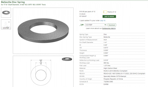
Here is the data on this spring:

1689281740942.png


My understanding is that these springs are fairly linear up to their working load and then dog leg sharply to the flat load. In the double stack configuration, the force is doubled and travel remains the same. The 7 sets of double stacks increases travel 7x. I think I should be able to add more stacks of springs to increase travel and reduce the tension loss due to the need for overtravel. The 33% increase in cylinder pressure should also allow me to get the drawbar much tighter while still having a reliable release. I'm hoping to fit 10-12 double stacks but we will see.

I'll be machining a new, longer drawbar to permit me to add as many stacks as reasonable without increasing the total spindle stack height too much (worried about vibration).
 
Back
Top