Mike's CNC G0704 - Block 4 Upgrades

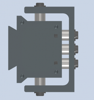
Did some quick calcs on the belleville disc spring stack. I should be able to increase the stack height from 0.99" to 1.88" with a new drawbar and no other changes made.

My current arrangement is a 7x2 stack of McMaster Carr 9712K437 that looks like this ))(())(())(()). In this configuration we have the following:
  • Working Load: 1800 lbs
  • Flat Load: 2544 lbs
  • Deflection at working load: 0.133"
  • Deflection at flat load: 0.168"
This does reliably clamp the tool holder but could be better. I'd like to measure the actual clamping deflection to understand exactly what tool retention I'm getting in practice. This is the most important number that I don't have.

In theory, simply increasing the number of power drawbar cylinders from 3 to 4 would give a 450 lbf tension increase since I could make the drawbar tighter and still reliably release the tool.

Fortunately, all the other options I considered also use the same belleville disc spring so I have options. Unfortunately, McMaster Carr doesn't seem to have another part number that is incrementally better than this one. It is an unusual combination of small diameter, high spring rate, and long travel.

My next concept is to keep the double stack arrangement, but increase the number of stacks to increase travel. With the new drawbar I could fit a 13x2 stack that looks like ))(())(())(())(())(())(())(()). In this configuration we have the following:
  • Working Load: 1800 lbs
  • Flat Load: 2544 lbs
  • Deflection at working load: 0.247"
  • Deflection at flat load: 0..312"
We don't actually need more travel, but this allows us to make the working tension on the drawbar MUCH higher while still reliably releasing tools. I need to take a measurement on my spindle for how much travel is needed to release tools in order to quantify exactly how much tension is gained in this configuration.

Finally I can rearrange the stack into a 9x3 configuration looking like this )))((()))((()))((()))((())). This slightly increases travel over my current setup, but greatly increases the working loads.
  • Working Load: 2400 lbs
  • Flat Load: 3816 lbs
  • Deflection at working load: 0.171"
  • Deflection at flat load: 0.216"
  • Deflection at 90 psi, 4 stack cylinder: 0.152"
In this configuration, its unlikely we will even see the springs reach their working load with the upgraded capabilities of the cylinder, but the stack has more travel than the initial configuration and significantly more tension force on the drawbar.

I can take some measurements of the existing drawbar setup when I reassemble the spindle and that will provide me the info I need to make some theoretical predictions about what stack configuration is better. The good news is that both new stack configurations would use the same drawbar and spindle top hat geometry, so I could easily reconfigure them and test both.

Between the increased stack height and the extra stage on the air cylinder, I'd expect roughly double the drawbar tension that I get today.

I could also just increase the stack height and skip the extra cylinder stage, but what is the fun in that?
 
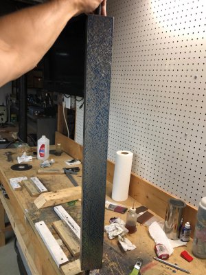
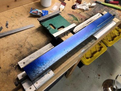
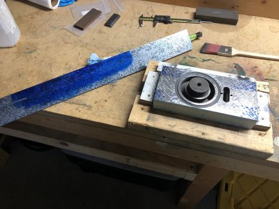
Marking with blue is surprisingly not helpful at identifying some forms of global curvature on a part.

Yup.

The main difficulty with “reading the blue” is that a part can rock on the plate as you mark it up, making the markup invalid. The only time you can be absolutely certain there is no rocking is if only three points touch.

Hinging is one countermeasure to see if this is happening.

If a convex side is down, it will spin like a top if you push either end. Very easy to detect.

If a concave side is down, it will hinge on the very outermost opposite points when you push either end.

If it’s dead flat, it will hinge roughly 30% in from the ends.

Note that hinging is also a useful technique locally as well as with an entire part on the plate. If you put an appropriately sized gauge block (or any lapped flat bar shaped object) on an area you are scraping, you can check whether that local area is flat.


Technically, I think a flat beam will hinge at it’s Bessel points but in practice “roughly 1/3rd in from the end” is good enough.

The shape of the part matters, though. If it isn’t a uniform bar shape, it will tend to hinge at the thicker/wider/heavier points, which is one reason to check locally with a gauge block.

Flat is surprisingly complicated. Even a 4” thick granite surface plate will sag and gradually conform to whatever surface it sits on (which is why you want to support it on three points). All bets are off if your reference surface isn’t sufficiently flat.
 
Last edited:
I have finalized my column design based on the feedback I received here and my original plan which I talked myself away from.

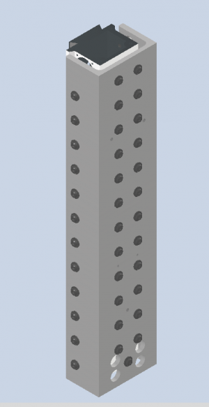
The column will be rigidly bolted to the MC channel at 48 (!) locations using precision sized steel spacers. Since I cant guarantee the channel or column will be a repeatable size, I will measure the column width and channel inside width at each bolting location and fabricate the spacer on the lathe to the exact size needed. Obviously I cannot get everything perfect to the thousandth, so there will be some deformation of the channel and column, however I am hopeful that having as many bolting locations as I do will average out the stresses and limit column deformation.

1689686653641.png

The steel tubing I bought is 3/4" OD and 3/8" ID. I'm hoping that I don't need to expand the ID for a 3/8" bolt, but even if I do, the small premium for the tubing will pay off in time saved. The channel walls are slightly tapered (although not nearly as much as normal C channel) so there will be a 0.023" height difference from one side of the spacer tube to the other. I'm hoping I can just ignore this. The back of the column and back of the MC channel are both flat.

I don't love the aesthetic of cap screw heads sticking out from the side of the column, but I need the play in the loose fit clearance bolt holes to correct for drilling errors from manual drilling. Flat head screws would have looked cleaner, but they self center and would create lots of twisting stresses with any misalignment. I at least went with low profile cap screws to reduce the stickout.

1689686697351.png

The column will still be filled with something, but with how thin the section is, and how many standoffs are now in the fill path, I'm questioning if I could even get epoxy granite mix into the cavity if I wanted to. If the epoxy is made thin enough to flow, then the aggregate mix is too dispersed to realize the strength benefits. I'm leaning back towards the expanding grout (mixed thin) or just loose sand. All the options will need to be vibratory settled to fill the column. The poured material is back to being a vibration damping agent and extra mass, rather than a structural element.

Total column weight is estimated at 106 lbs, a 225% increase over the original 47 lbs.

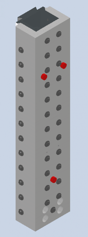
I'll let this fully settle before scraping the ways to precision alignment. On that topic, I've included (3) cast iron pads permanently threaded and Loctite'd into the column which can be scraped as a check surface parallel to the flat ways. This will permit me to flip the column on its back and measure the ways with an indicator. The pad locations are 22% in from each end forming a kinematic 3 point mount. Pads are shown in red. These will need to be covered with protective caps to prevent any damage to this precision reference surface.

1689687181554.png

I have a ton of holes to drill, so I bought nice split point cobalt screw machine drills to do all the tap drills and clearance holes. hoping the drill press can punch these out easy enough. The column will also become swiss cheese with this operation. Hope it is worth it, because a new column is $250.
 
Scraping the Straightedge (Part 2):

Didn't take any more in-process photos, but I finished scraping the wider face of the angle straightedge. I think this is the only face I need for the time being as the other face is only needed for clearance. I would guess this took about 20 passes and 5-6 hours of effort to get to where it is. Bearing is nearly even density across the entire face, coverage is in the 20-40 PPI range, and the face hinges at the 25% locations nicely.

image100.jpg

The straightedge is already in use scraping the Z axis slide face (which has a boss above the flat surface). I'll detail exactly how and why this is done in a future post.

image101.jpg

The gouge in the face is far enough away from the knife edge that it will not affect anything on this scraping project.
 
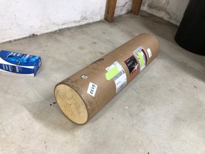
Also amusingly, this is the tube that Coremark Metals shipped me the MC channel in. It is enormous! Took me 30 minutes to pry off one solid wood end cap and get the channel out.

image102.jpg

Didn't save any photos of the process, but I scrubbed down the entire channel with Evaporust and Scotchbrite to clean off the rust and some scale. I'll be painting the column when finished.
 
Z Axis Slide Scraping (Part 1)
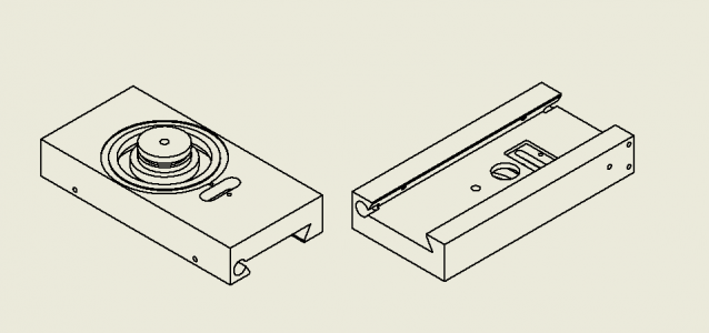
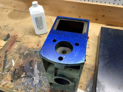
With the head casting and straightedge now scraped, I can start on the Z axis casting. I won't be able to finish it until the column is complete, but I can do the flat faces. The Z axis slide is challenging because of the circular boss sticking up from the face which mates with the mill head casting. This boss permits the head to be rotated for angular operations.

1689771998455.png

The mill head casting will be used extensively as a spotting template for the Z axis slide, however it is actually a fairly poor template to spot from. First of all, it does not cover the entirety of the surface, and this is allowed to cam up and down on the surface as it is rotated. Secondly, the head casting has the large rectangular hole which obviously carries no blue to transfer to the Z axis slide. This means that only the thin webs on either edge can mark the slide and are very quickly depleted of blue to transfer. For this reason, high spots that are within the radial annulus of the rectangular window are marked so faintly that they almost are imperceptible.

image110.jpg

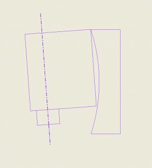
I've tried to illustrate the camming issue with marking using only the head casting. I know the head casting to be true to the spindle centerline, and the Z axis slide is quite convex (exaggerated in this depiction).

Z Axis Slide Start.PNG

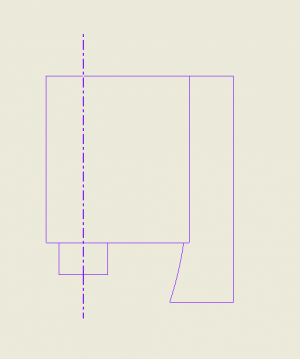
With marking only with the head casting, I might be able to get the scraping flat and true (would be quite difficult due to the rectangular window).

Z Axis Slide Scraped with only Head.PNG

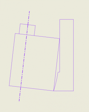
But any rotation of the head (show completely inverted here, because it is a 2D sketch) would cause the head to cam over the surface and not provide a straight spindle centerline. Since the head casting is smaller than the slide, I cannot use it to guarantee the entire surface is flat, especially along the long edge.

Z Axis Slide Rotated.PNG

For this reason I believe I need to use many different methods to spot and measure the casting to ensure it is a truly flat surface all over, and the spindle centerline be parallel to the XZ plane at any rotation angle. In the image below, I am showing how I am using the freshly scraped straightedge to mark the casting, showing convexity across the long direction. This can only show local geometry along the edge and would easily mask twist without another method.

image104.jpg

I'm using the small 6x9 Grade A surface plate shown here to mark the shorter widthwise direction. I can only use this to improve bearing and fix convexity, but it is so small that it will very easily mask twist.

image103.jpg

Printing with the head casting should show twist, but I will also be regularly indicating the surface on the surface plate to identify twist and parallelism to the flat ways on the opposite side.

Here is the surface, spotted with multiple tools, at a mid to late stage roughing cycle (14 passes). Contact is present all over, but fairly absent from the 2 annular contact rings around the boss. These rings represent the majority of the contact to the head casting and need to be brought into full bearing. The blue is very heavy to keep me from getting into finishing too early (a bad habit of mine)

image107.jpg
 
McMaster Carr delivered quite the goodie box of parts for the machine. I forgot how much screws and washers add up! Waiting on a couple more items and I'll be good to continue with the column.
 
Those diagrams were very helpful.

I think your approach to bluing makes complete sense, but you could also do final checks by marking up with the mill head casting at various rotations. Ultimately, those are the surfaces that must mate well at all orientations, so marking against one another is the ultimate proof of bearing.

For example, one blue up at 0 degrees, one at 30, 60, 90. Just small motions to transfer the blue at each orientation. Basically mimicking the motion of the head in use on the mill: trammed, and tilted at various attitudes.
 
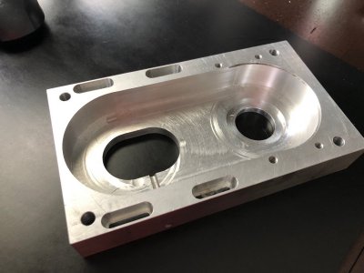
Spindle housing was returned by my buddy after having the inner cavity opened up, as well as the motor pulley slot.

image115.jpg

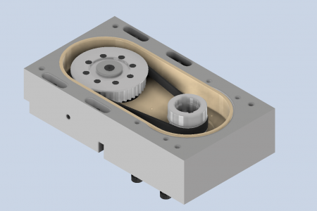
Here is an upside down view of how the pulleys assemble into this housing

1689787164687.png

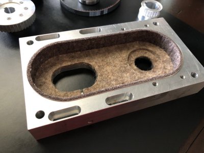
One of the last minute modifications was to include some F7 grade wool felt into the design for noise reduction. Much of the design of this housing originally was to keep the spindle as quiet as possible, and the change to a 10,000 rpm spindle is going to increase noise. The felt sheets will cover 5 out of 6 sides (could do the casting face too, but it would be complicated to assemble). The felt is purely for acoustic damping of the belt noises, which seem to be the predominant source of sound in the system.

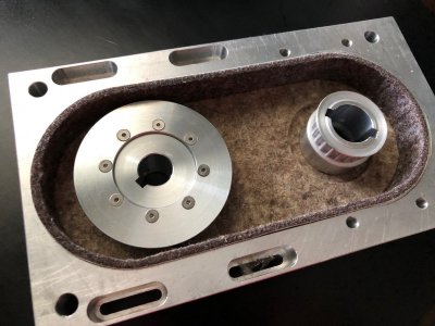
Here is a mockup of the felted interior. The felt is adhesive backed and rated to 200*F. The upper sheet will be retained by some flat head screws since it will be fighting gravity. The top sheet also locks the perimeter sheet into place so it shouldn't want to peel away from the walls. The smallest circular opening on the right is the only place where there is exposure to atmosphere and the ID of the felt ring will rub against the power drawbar top hat to make an acoustic seal. This is how it has been running for a few years and that works great. The felt is not abrasive on the 4340 steel .

image113.jpg

And a mockup of the pulleys in their installed locations.

image114.jpg
 
Back
Top