My ACRA 1440 TVS

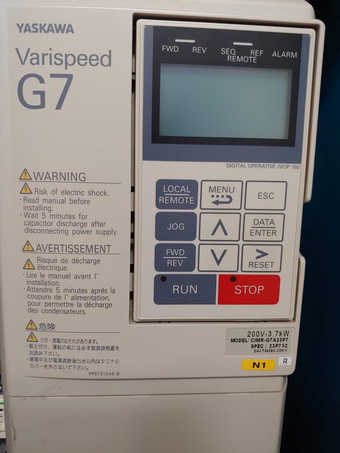
The electrician should review the size of the VFD and derating for single phase. It is definitely rated for single phase, and I would not run it off of the RPC. There is also the issue of the wild leg on the RPC could damage the control electronics due to voltage fluctuations. If the electrician still has concerns he should contact Acra, or email them and show that to your electrician.
 
This is what he saw, and did. The manuals did not seem to give him much guidance.


I would contact Acra for guidance. The VFD is rated at 3.7 kW which is 5 Hp, they are suppose to be 5.5kW to run on single phase with a 5 Hp motor.
 
I sent Tom an Email, and I'm waiting for a response.
 
I was looking through the online manual(about 1000 pages I think)., and in the overview I saw this.
Service Conditions

  • Enclosure: NEMA 1 or protected chassis
  • Ambient service temperatures:
    -10 to 40°C (104°F) NEMA 1,
    -10 to 45°C (113°F) protected chassis
  • Input frequency: 50 / 60 Hz ± 5%
  • Input voltage: +10% / -15%, 3 phase, 240 or 480 VAC, phase insensitive
  • Humidity: Non-condensing, 95% maximum
  • Altitude: 3300 feet (1000 meters) w/o derate
  • Vibration: 1G (10 to 20 Hz), 0.6G or less (20 to 55 Hz)
 
Last edited:
The only thing you have to do is land the plug wires, 2 hots and a ground to R, S, & the ground from the plug on E. Bottom left of the terminal strip.
 
Unfortunately it appears that they have changed the VFD drive rating. I had another person who bought the same lathe and I asked him to verify with Acra that it could also run on single phase, and he was told it could. But the VFD in the picture is a 3.7 kW model 3 phase input, so in derated mode on single phase it will not be able to run a 5 Hp motor. Based on the rating on the VFD/model ir would need to run off an RPC, the wild leg should not be attached to the transformer which are the R and T wires.
Yaskawa Varispeed G7 Inverter Cimr-G7A23P7 3Ph 200V 3.7K
 
The green is wired to the frame, where do the red, black, and white go? He has them going into the on off switch in the door.
 
Last edited:
It is wired correctly if coming from the RPC, the wild leg would be connected to the red wire "S" as R and T go to the transformer. The green wire is grounded to the box as you have it. There different interlocks so the belt cover needs to be on and if equipped with a shield guard it needs to be down. There is usually either a power lock button the energizes the power contactor and/or the spindle switch needs to be in the stop position.
 
Thank you, so it's ready to run, is there a need to stabilize voltage from the RPC?
 
Back
Top