My First Lathe - HF 9" x 20"

From my understanding you need to go very slow for cast iron with HSS. Need to keep the SFM to 50-60. SFM = RPM * pi * D/12. D is the diameter in inches & 12 converts from inches to feet. Solving for RPM = 12 * SFM / (pi * D) = 12 * 50 / (3.14 * 6) = 31.8 RPM. I'd bet you were going a lot faster than that! Didn't you say your minimum RPM was 100? Way too fast for HSS and 6" cast iron.

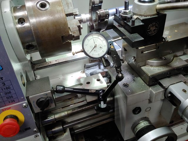
Correct. On the chart that the lathe has for the speed combinations, the slowest it would go is 120. Measured by the RPM display, it is actually going at 145 rpms... So very fortunate the lathe came with those tool bits with the carbide tip brazed on them...

I am taking very small cuts... this will take me awhile, but it is working so far...

Red lines show where I need to get to... not to scale, of course...lol

IMG_2471.jpeg


Tool bit I have been using...

IMG_2472.jpeg


And got this cheap set today to test...

IMG_2473.jpeg


Thinking of taking a break from reducing the outer diameter and working on reducing the inner diameter... that is the section that goes into the recess on the chuck... Yeah, I just want to try using a different tool bit, hehehehe
 
This was easy... Took it to the mill for the slot and then drilled and used a 5mm tap for the threads...

View attachment 380014

View attachment 380015

Nothing else to do but to start bringing it to correct dimensions... I need to get the shower curtain first... I already have the brush and will make a mount for putting it on a magnetic base...
Why did you do this? Are you planning to reverse turn?

I'm looking at another lathe, and it has a similar threaded connection. Was wondering if something like this could be used for reverse thread cutting or not. I've single pointed internal threads with a left hand tool and the lathe in reverse. That way the tool goes away from the chuck. A lot less frightening, especially if there's an internal stop.
 
You speak to me as if I knew what I was doing :D ...

The other chuck had it... so I made this one the same. That is as far as I can explain my reasoning for doing that modification, lol...
 
Working the inner section… Look! A mechanical DRO :)


74A92FAE-B2E9-45F4-B153-0F6264707697.jpeg
 
Working the inner section… Look! A mechanical DRO :)


View attachment 380146
For the future, you should attach the mag base to either the headstock, or the ways. If the lathe shifts relative to the table you lose precision. Far more accurate if the base is attached to the headstock. The base may stick right through the label on the front. On top is a better bet if your Noga (clone?) can reach that far.
 
For the future, you should attach the mag base to either the headstock, or the ways. If the lathe shifts relative to the table you lose precision. Far more accurate if the base is attached to the headstock. The base may stick right through the label on the front. On top is a better bet if your Noga (clone?) can reach that far.
Lathe is bolted through the top of the bench… is not moving… ;)

But I do plan on making the mods @Steve-F made to install the dial indicators right on the lathe… he shared photos on this thread.
 
Last edited:
Not to be a wise guy, but what is the bench made out of? If wood, it's moving :) Seriously, it is better to attach the indicator on the headstock. Probably no better reference, assuming your bearings are ok.
 
Not to be a wise guy, but what is the bench made out of? If wood, it's moving :) Seriously, it is better to attach the indicator on the headstock. Probably no better reference, assuming your bearings are ok.

Understood. I will try to do that next time. I am working within a very limited amount of space and placing it on the metal bench top (the countertop is actually a wood panel that is covered with sheetmetal). I really did not take the time to figure out a way to place it on the lathe... I took the easy way out this time.

Hopefully, after all this is done, I will be making mounts, for both axis, to mount dedicated dials, like what Steve did.

The good news is that one task is done. I can install the chuck... a good and snug fit.

IMG_2476.jpeg


Next task is to finish bringing the outside diameter to size...

IMG_2479.jpeg


Then I will need to figure out how to locate/mark the holes... that is going to be fun...

Took the time to clean everything...

IMG_2482.jpeg


Will cover everything again and do the rest of the cutting...

IMG_2483.jpeg


That is all for tonight...

IMG_2488.jpeg
 
Last edited:
Back
Top